Graphics Programs Reference
In-Depth Information
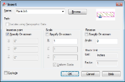
Figure 17-3:
The Insert dialog box.
3. Enter the block definition name (or external filename) by using one of the fol-
lowing methods:
• Use the Name drop-down list to select from a list of block definitions in the
current drawing.
• Click the Browse button to select an external DWG file and have AutoCAD
create a block definition from it.
You can use an external drawing to replace a block definition in your current draw-
ing. If you click Browse and choose a file whose name matches the name of a block
definition that's already in your drawing, AutoCAD asks you to confirm the update
and, if you agree, updates the block definition in your drawing with the current con-
tents of the external file. This process is called
block redefinition,
and AutoCAD
automatically updates all block references that point to the block definition.
4. Enter the insertion point, scale, and rotation angle of the block.
You can either select the Specify On-Screen check box in each area to specify the
parameters on-screen at the command prompt, or type the values you want in the
text boxes in the Insertion Point, Scale, and Rotation areas.
Select the Uniform Scale check box to constrain the X, Y, and Z scaling
parameters to the same value (which is what you want in almost all cases).
5. If you want AutoCAD to create a copy of the individual objects in the block in-
stead of a block reference that points to the block definition, select the Explode
check box and click OK.
6. If you selected the Specify On-Screen check box for the insertion point, scale, or
rotation angle, answer the prompts on the command line to specify these paramet-
ers.