Graphics Programs Reference
In-Depth Information
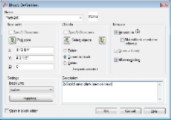
The Block Definition dialog box appears (see Figure 17-1).
Figure 17-1:
The Block Definition dialog box.
Pay attention to layers when you create the objects that make up a block.
As a rule, block geometry created on most layers retains the color, linetype, line-
weight, transparency, and plot style properties of those layers. The exception to the
rule is object geometry created on Layer 0. If you create a block using geometry
drawn on Layer 0, then the block takes on the features of any layer into which you
insert it.
2. Type the block definition's name in the Name text box.
If you type the name of an existing block definition, AutoCAD will warn you when
you click OK at the end of the process and ask if you want to replace that block
definition with the new objects you select. This process is called
block redefinition.
To see a list of the names of all the current blocks in your drawing, open
the Name drop-down list.
3. Specify the base point (also known as the insertion point) of the block, using any
of the following methods:
• Enter the coordinates of the insertion point in the X, Y, and Z text boxes.
• Click the Pick Point button and then specify a point on the screen. (In this
case, use an object snap or other precision technique, as described in
Chapter 7, to grab a specific point on one of the block's objects.)
The
base point
is the point on the block by which you insert it later, as I describe in
the next section.