Graphics Programs Reference
In-Depth Information
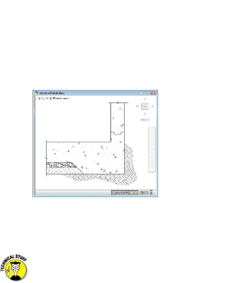
Drafters often use hatching to represent the type of material that makes up an object,
such as insulation, metal, concrete, and so on. In other cases, hatching helps emphasize
or clarify the extent of a particular element in the drawing — for example, showing the
location of walls in a building plan or highlighting a swampy area on a map so you know
where to avoid building a road. Figure 15-1 shows an example of hatching in a structural
detail.
As I mention in Chapter 13, hatching is another component of AutoCAD's annotative ob-
jects. Hatch patterns have a scale factor (as I explain in the “Getting it right: Hatch angle
and scale” section, later in this chapter) and can be created so that the hatch scale up-
dates as the annotation scale changes.
Figure 15-1:
A big batch o' hatch.
An AutoCAD
hatch
is a separate object that fills a space, has an appearance dictated by
the hatch pattern assigned to it, and by default is associated with the objects that
bound the space, such as lines, polylines, or arcs. If you move or stretch the boundaries,
AutoCAD normally updates the hatching to fill the resized area.
Hatch patterns are defined by external files named
acad.pat
or
acadlt.pat
(imperial units), or
acadiso.pat
or
acadltiso.pat
(metric
units). Each file includes definitions for eight ANSI hatch patterns (mostly vari-
ations on diagonal lines), 14 ISO patterns, and 50 other predefined patterns. (I re-
commend you avoid the ISO patterns for the same reason as I suggested you stay
clear of ISO linetypes in Chapter 6.) You can create your own hatch patterns —