Graphics Programs Reference
In-Depth Information
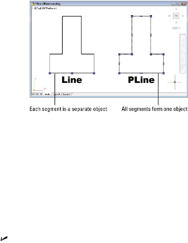
Figure 8-3:
Results of drawing with the LINE and PLINE commands.
Use PLINE instead of LINE in most cases where you need to draw a
series of connected line segments. If you're drawing a series of end-to-end seg-
ments, there's a good chance that those segments are logically connected — for
example, they might represent the outline of a single object or a continuous path-
way. If the segments are connected logically, it makes sense to keep them connec-
ted in AutoCAD. The most obvious practical benefit of grouping segments together
into a polyline is that many editing operations are more efficient when you use
polylines. When you select any segment in a polyline for editing, the entire poly-
line is affected.
The PLINE command can draw curved segments as well as straight ones.
If you
want a combination of separate linear and curved segments you must switch back
and forth between the LINE and ARC commands (I cover arcs in Chapter 9). With
PLINE you can switch between linear or circular-curve sections by choosing the
command options described in the steps that come after this list.
Polylines can have width.
Polyline segment width is visually similar to AutoCAD's
lineweight object property, except that polyline segment width can be uniform or
tapered. The ability to create polyline segments with line widths was more import-
ant in the old days, before AutoCAD had lineweight as an object property. People
used to draw polylines with a small amount of width to show the segments as just
slightly bolder than regular lines, which are always displayed as a single pixel
wide. Nowadays, it's easier and more efficient to achieve this effect with object
lineweights (as described in Chapter 6) or plot styles (as described in Chapter 16).