Information Technology Reference
In-Depth Information
LAN / WAN
T
I
E
R
I
n
t
e
r
n
e
t
Client
workstation
Client
workstation
Client
workstation
Client
workstation
Client
workstation
1
Client
workstation
Client
workstation
Client
workstation
Client
workstation
Client
workstation
T
I
E
R
LAN / WAN
2
Servers
T
I
E
R
3
Servers
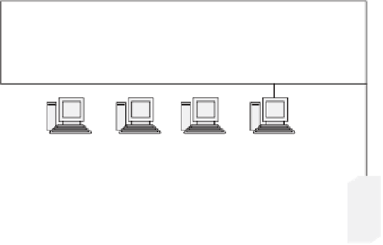
Figure 14.7
Architecture for a complex 3-tier application
The main difference between Figure 14.4 and Figure 14.7 is that there are more
distinctly different groups of computers with distinctly different tasks. The identifi -
cation of the different groups becomes more diffi cult as the number of different tasks
multiplies and, in some cases, overlap. We suggest an approach to identifying these
groups that works well but is not the only successful way. As long as the rationale
behind your approach is technically consistent and reasonably unambiguous, your
test planning can succeed.
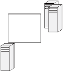
We suggest grouping the Figure 14.7 components into three tiers: browser tier,
security tier, and application tier. Figure 14.8 shows the grouping of components into
these three tiers.
The browser tier in the 3-tier example is analogous to the client tier in the 2-tier
example. It provides the end-user screen interface for running the application. The
security tier in the 3-tier example is analogous to expanded tier-to-tier connectivity
functionality in the 2-tier example. The application tier in the 3-tier example is
analogous to the server tier in the 2-tier example.
As we saw with the 2-tier example, the secret of test planning success is the test
team's involvement in and understanding of the development team's functional design
of each tier. For example, some development teams might design the web home page
server as mainly a security function like logging onto the web application, basically


Search WWH ::

Custom Search