Environmental Engineering Reference
In-Depth Information
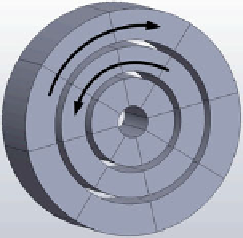
Fig. 3.35 A double Halbach array, which was for instance applied in magnetic refrigeration by
Tura and Rowe [
49
,
50
](a ON eld position, b OFF eld position)
Halbach array (presented in Fig.
3.35
). The problem that characterized the double
Halbach solution was in the actual magnetic
fl
ux density at low
eld, which was not
zero (having an average high-
eld magnetic
fl
ux density of 1.34 T and an average
low-
ux density of 0.57 T [
53
]). This, of course, is not desired. As
stated further by Arnold et al. [
53
], the total
eld magnetic
fl
eld vector orientation inside the AMR
volume rotated, which could induce additional rotational forces and eddy currents.
The new magnet design of a triple Halbach array with the increased number of
magnet segments in each ring (each ring comprised 12 segments of magnets
—
not
shown in Fig.
3.36
) improved the homogeneity and the magnetic
ux density. The
two outer magnetic rings rotated in the counter direction with respect to each other,
while the inner magnetic ring was static. In this way a sinusoidal
fl
eld waveform
was produced. In analogy with the previous solution, the three rings, when their
vector of the magnetic
fl
ux density was aligned, lead to the maximum magnetic
fl
ux
density in the bore. When the two outer rings were rotated by 180
°
C with respect to
the inner static ring, the magnetic
fl
ux density vectors cancelled each other, thus
Fig. 3.36 A triple Halbach array with two outer magnetic rings rotating in the counter direction
and with the inner static magnetic ring (see also Arnold et al. [
53
])

Search WWH ::

Custom Search