Environmental Engineering Reference
In-Depth Information
Furthermore,
the amount of current
fl
owing through is proportional
to the
thickness of the cross-section:
N
L
Idz
0
¼
nIdz
0
¼
ð
3
:
81
Þ
dI
The magnetic
eld at point P can now be de
ned as:
l
0
a
2
2
dB
¼
dI
ð
3
:
82
Þ
2
2 a
2
þ
ð
z
0
Þ
z
By taking into account Eqs. (
3.81
) and (
3.82
), the integral over the whole length
of the solenoid will lead to the following magnetic
fl
ux density at the point P.
L
2
Z
l
0
nIa
2
2
dz
B
ðÞ¼
3
2
2
a
2
þ
ð
z
z
0
Þ
L
2
ð
3
:
83
Þ
2
3
L
L
l
0
nI
2
z
z
2
z
z
þ
2
þ
4
5
¼
q
þ
q
2
2
L
2
L
2
þ
a
2
þ
a
2
ux
density. Therefore, in practice the coil will consist of several layers (Fig.
3.20
)of
wires (or a layer of a run with a certain thickness, such as for instance in so-called
Bitter magnets, see Fig.
3.21
).
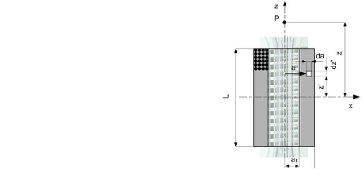
By taking Eq. (
3.82
), we can rearrange it for this particular case. Now, we deal
with the 2D problem, by adding the length a as the variable, by taking values from
a
1
to a
2
.
A single layer of wire will, in practice, not provide suf
cient magnetic
fl
Fig. 3.20 The solenoid
comprising several layers of
turns


Search WWH ::

Custom Search