Environmental Engineering Reference
In-Depth Information
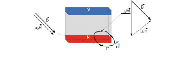
Fig. 3.10 Vectors on the path
Γ
on both sides of the magnet-air boundary
surrounded only by air, since there are no currents, Eq. (
3.11
) takes the following
form:
Z
H d
l
¼
0
:
ð
3
:
57
Þ
C
The term in Eq. (
3.57
) can also be considered as the magnetomotive force [
14
].
Let us consider a path
Γ
that passes the boundary between the bar magnet and the
air (Fig.
3.10
). If we apply Eq. (
3.57
) for this particular case, then we obtain:
Z
Z
H d
l
H dl
þ
¼
0
ð
3
:
58
Þ
C
magnet
C
air
eld
in the air gap. Another important relation regards Eq. (
3.15
), which shows that the
magnetic
The negative magnetic
eld in the magnet will lead to a positive magnetic
ux density is preserved over the considered surface of the material.
Together with Eq. (
3.58
), these two equations can be used for the design of the
magnetic circuit. Let us consider an example of a simple permanent-magnet
assembly, which consists of soft iron (which is used to guide the magnetic
fl
fl
ux) and
the permanent magnet (Fig.
3.11
).
In Fig.
3.10
we consider an in
nitely permeable soft iron material; therefore, no
heat-
eld outside the magnet assembly
will equal to zero. The air gap between the two poles of soft iron has a cross-section
area A
gap
and its length is de
fl
ux leakage will occur and the magnetic
ned to be L
gap
. In Fig.
3.11
, the permanent magnet,
attached to the soft iron, has a cross-section of A
mag
and its length is L
mag
. By using
Eq. (
3.15
) and considering no leakage into the surroundings, Eq. (
3.15
) can be
rewritten as:
B
mag
A
mag
¼
B
gap
A
gap
ð
3
:
59
Þ
Now, by applying Eq. (
3.59
), this can be rewritten for our particular case as:
Search WWH ::

Custom Search