Environmental Engineering Reference
In-Depth Information
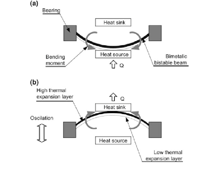
Fig. 10.20 Bimetallic micro heat engine for pyroelectric energy conversion, a The pyroelectric
material is in thermal contact with the heat source, b The pyroelectric material is in thermal contact
with the heat sink (see also Ravindran et al. [
70
])
from the beginning. In the experiment, a 200-
m-thick commercially available
piezoceramic Vibrit 1100, which also exhibits pyroelectric properties, was used.
The temperature difference between the heat source and the heat sink was varied
between 45 and 80 K and the device was operating between a frequency (de
µ
ned as
the number of thermodynamic cycles per unit of time) of 0.1 and 0.42 Hz.
A maximum power output of the pyroelectric element of 3.03
W was measured for
a temperature difference of 79.5 K and a frequency of the device equal to 0.42 Hz.
Ravindran et al. [
70
] presented an additional, similar concept to the one
described above. In the centre of the device is a pyroelectric material attached to a
bimetallic strip, as seen in Fig.
10.20
. On each end the bimetallic strip is mounted
on a bearing and placed between a heat sink and a heat source. When the bimetallic
strip is in physical contact with the heat source (Fig.
10.20
a), the heat is transferred
from the heat source to the bimetallic strip by means of heat conduction. As a result,
the bimetallic strip heats up, which causes a bending moment in the strip that moves
from the heat source to the heat sink (Fig.
10.20
b). Now the bimetallic strip is in
physical contact with the heat sink and the heat is transferred from the bimetallic
strip to the heat sink. In this way, the bimetallic strip cools down and moves back to
its original position (Fig.
10.20
a). This cycle is repeated many times and a sort of
oscillatory movement of the bimetallic strip is established. Since the pyroelectric
µ
Search WWH ::

Custom Search