Environmental Engineering Reference
In-Depth Information
Table 10.5 Chip-sized electrocaloric cooling device and its properties
Name and address of institute
The Pennsylvania State University
Name of contact person/email
Qiming Zhang
qxz1@psu.edu
Year of production
2012
Maximum frequency
1 Hz
Maximum cooling power
N/A
Maximum temperature span
6.6 K
EC material
High-energy electron-irradiated
P(VDF-TrFE) 68/32
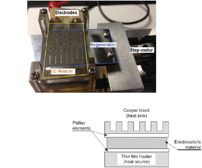
Fig. 10.13 Electrocaloric
cooling device by Chukka
(see also [
55
])
sink. On the bottom side, a thin-
lm heater with 10 W of power (heat source) was
positioned. Additional temperature sensors were inserted between the thin-
lm
heater and the electrocaloric material and between the electrocaloric material and
the copper block. In the
rst-case scenario, the device was heated up to 85
°
C (by
turning on the thin-
lm heater). Then the heater was turned off and the time needed
for the sandwich-like structure to cool down to ambient temperature was measured.
In this case, the electrocaloric material was not subjected to a varying electric
eld.
In the second case scenario, the sandwich-like structure was again heated up and
after it had reached the desired temperature of 85
lm heater was turned
off. However, this time, after the heater was turned off, the electrocaloric material
was subjected to a rectangular electric signal (thereby inducing the electrocaloric
°
C, the thin-


Search WWH ::

Custom Search