Environmental Engineering Reference
In-Depth Information
Table 9.6 Geometry of the regenerator with a 60%volume fraction of magnetocaloric material [
36
]
Spheres diameter d = 0.25 mm
L = 5 cm
L = 10 cm
L = 15 cm
Mass of MCM material (kg)
298.43
596.85
895.28
Parallel plates thickness s = 0.25 mm
L = 20 cm
L = 30 cm
L = 40 cm
Mass of MCM material (kg)
1193.7
1790.55
2387.4
MC material: ideally layered La (Fe, Si, H) material;
Magnetocaloric structure: Coaxial cylinder with volume fraction 60 % (see
Table
9.6
);
Magnetic
eld change: 1.5, 2 and 3 T.
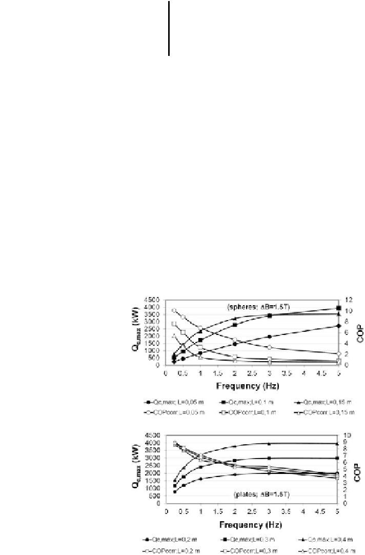
Figure
9.13
shows the maximum cooling power and the corresponding COP as a
function of frequency for the magnetic
eld change of 1.5 T for the AMR consisting
of spheres (top) and for the AMR consisting of plates (bottom). As can be seen from
Fig.
9.13
(top), the maximum cooling power may be obtained for AMRs with
lengths between 10 and 15 cm. It is further evident that the increase in the length of
the regenerator from 10 to 15 cm leads to a decrease in the cooling power at
frequencies above 3 Hz. Also, the COP is very low at frequencies above 3 Hz and
cannot be comparable with that of compressor chillers. As can be also seen from
Fig.
9.13
(top), the highest COP is obtained for the shortest packed-bed AMRs (for
a given temperature span).
Fig. 9.13 The maximum
cooling power and the
corresponding COP as a
function of frequency for the
AMR with spheres (top) and
for the AMR with plates
(bottom) under a magnetic
eld change of
μ
H
0
= 1.5 T
Δ
0
[
36
]


Search WWH ::

Custom Search