Environmental Engineering Reference
In-Depth Information
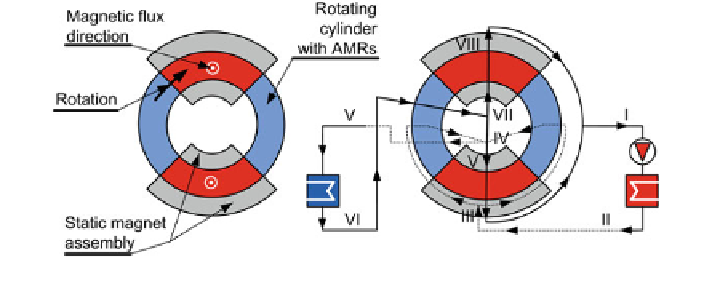
case a closed arrangement can also be constructed. According to Fig.
8.12
, the
magnet assembly has to provide the magnetic
ux in the direction of the observer of
the system (direction of the central rotating axis of the coaxial ring with AMRs).
The
fl
ow is therefore usually directed from the central axis in a radial direction
through the AMRs or vice versa, from the outer diameter towards the centre of the
device. Similar as in the case of Fig.
8.7
, we can describe the operation of such an
architecture.
According to Fig.
8.12
, the
fl
uid
fl
ows continuously through two, oppositely
positioned and interconnected AMRs, since these operate at the same temperature
level. Note, also, in this case that the entering of the working
fl
uid
fl
uid in the AMRs in
the magnetized state and demagnetized state has to be provided on opposite sides of
the coaxial AMR ring in the radial direction. The warm working
fl
uid that is leaving
the AMRs in the magnetized state enters the HHEX at position I. There it rejects
heat II to the environment and
fl
fl
ows to the
fl
uid distribution valve (not shown),
which divides
ow III and guides it in a radial direction through the AMRs in
the demagnetized state. The working
fl
uid
fl
fl
uid cools down in both demagnetized AMRs
and
fl
ows to the valve system (
fl
ow divider) IV, which directs the
fl
uid
fl
ow to the
CHEX V. In the CHEX the working
fl
uid heats VI since it absorbs heat from the
cooled environment and
fl
ows back to the valve system VII, which directs the
fl
uid
fl
ow in the radial direction to both magnetized AMRs. In those AMRs, the working
fluid absorbs the heat VIII and flows towards the CHEX. Also, in this case, the
rotation of the coaxial structure with the AMRs can be continuous or discontinuous.
Figure
8.13
shows two ways of applying the magnetic
fl
ux direction through the
AMR. In the
rst case (Fig.
8.13
a), the parallel plates of the AMR have to be
arranged in the direction of the magnetic
fl
ux, i.e. in the radial direction. In the case
of Fig.
8.13
b,
ux direction is parallel to the axis of rotation.
Therefore, the parallel plates in the AMR have to be arranged in the same direction
with the magnetic
the magnetic
fl
ux.
As can be seen in this case, the length of the AMR is more restricted in radial
devices than in axial ones. Because of this the difference between the outer and
inner diameters of such a ring has to be suf
fl
ciently long (e.g. from about 50 to
Fig. 8.12 An opened magnet assembly of the rotary magnetocaloric device with the radial
fl
uid
fl
ow through AMRs, classication no: R20(3)0(5)(6)01111(12)
Search WWH ::

Custom Search