Environmental Engineering Reference
In-Depth Information
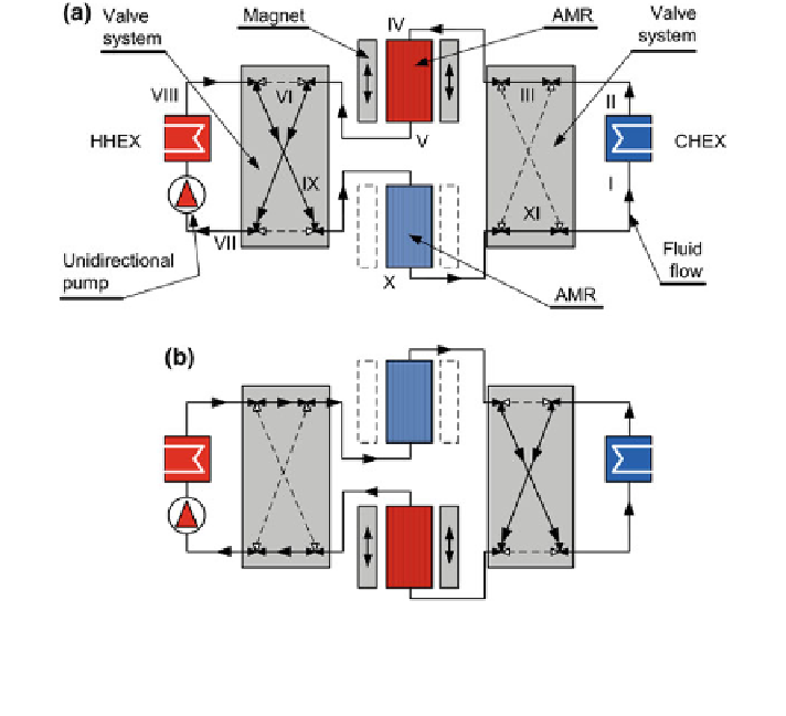
Fig. 8.3 A magnetocaloric device with a linear movement of the magnet assembly over two static
AMRs with the application of the switching-valve system and the uni-directional pump (a upper
AMR magnetized,
lower AMR demagnetized; b upper AMR demagnetized,
lower AMR
magnetized), classi
cation no: R20(3)1(5)(6)011001
II. From II it enters the switching-valve system III, which guides the fluid to the
AMR, which is in the magnetized state IV. There the
uid absorbs heat from the
AMR V and passes to the second valve system VI, where it is redirected to the
pump VII and HHEX. In HHEX it rejects heat to the environment VIII.
Then the
fl
fl
uid again enters the switching-valve system IX, which guides the
fl
uid
to another AMR, which is in the demagnetized state. The
uid cools down X and
enters the valve system XI. When the magnets move from the position in Fig.
8.3
a
to the position in Fig.
8.3
b, the valve system switches the directions of the
fl
fl
uid
fl
ow and thus provides a quasi-continuous production of cold. We denote it as
“
because of the fact that during the movements of the magnets, especially if
the AMR Brayton-like process is applied, this will require a certain time period.
If the magnetocaloric material moves instead of the magnetic
quasi
”
eld source
(Fig.
8.4
), this can be provided either with a static permanent magnet assembly or
with an electric coil. In the latter case, it of course makes sense to avoid any motion
(with
rst magnetic
refrigerators based on superconducting solenoids applied the motion of the mag-
netocaloric material in and out of the superconducting solenoid.
“
on-off
”
operation of the electromagnet). Note that
the
Search WWH ::

Custom Search