Environmental Engineering Reference
In-Depth Information
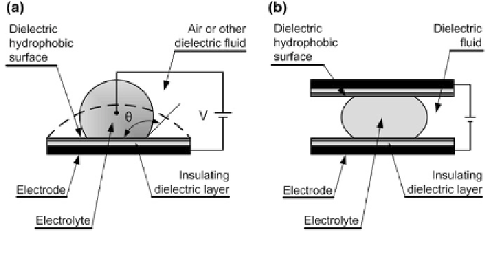
Fig. 6.15 Examples of electrowetting manipulation of
uid,
a electrowetting on insulator-coated electrodes (EICEs), b electrowetting on a dielectric (EWOD)
the surface tension of
the
fl
to the heat-sink and heat-source heat exchangers, respectively. During the mag-
netization cycle, the thermal diode mechanism is in the OFF-position on both sides
of the magnetocaloric material. The magnetocaloric material heats during the
magnetization. During the process of the iso
eld cooling, the upper series of
thermal diodes is switched ON, thus providing the contact between the heat sink
and the magnetocaloric material. The thermal diodes are then switched OFF and the
process of demagnetization is performed. Therefore, the magnetocaloric material
cools down. The lower series of thermal diodes is switched ON, providing a contact
for the heat
fl
ux from the heat source.
Electrowetting as the Manipulation the Electrocapillary Flow of the
Thermal Diode Mechanism
ow (Fig.
6.17
), the surface tension is based on
the electric potential that acts across an interface. Here, the velocity of the
In the electrocapillary-induced
fl
uid can
reach up to 10 cms
−
1
, or even higher in some applications. This is very high if we
take into account the microscale in which the thermal diode acts. The electro-
capillary
fl
fl
ow is many times referred to as one of the basic mechanisms for digital
micro
uidics [
91
,
92
].
In Fig.
6.17
a, planar parallel line electrodes (ELE) provide the spontaneous
electrowetting flow of the liquid lm [
93
]. A lm with a thickness of several
microns
fl
ows due to the elongated drop when the electric potential is applied over
the electrodes. The
fl
lm velocity is higher than the macroscopic spreading of the
drop itself [
94
]. The reason for this is the bulk electric pressure gradient in the
Search WWH ::

Custom Search