Environmental Engineering Reference
In-Depth Information
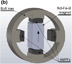
Fig. 3.39 The magnet assembly with the four rounded iron poles and four rounded AMRs and
with the rotating bar magnet (see also Bouchekara et al. [
56
])
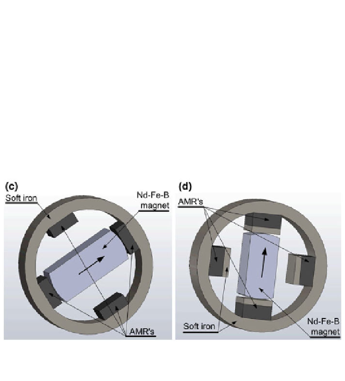
Fig. 3.40 The magnet assembly without iron poles, c the four rectangular AMRs are attached to
the smooth static iron ring, d the four rectangular AMRs are attached to the smooth static iron ring
and 10 mm steel is attached to AMRs (see also Bouchekara et al. [
56
])
of 10 mm were attached to the AMR beds. The idea here was to bring support that
would sustain tangential forces instead of the AMRs.
The magnet assemblies (e) and (f) in Fig.
3.41
comprise six poles each. The idea
behind the increased number of poles was that a larger number of poles reduce the
magnetic torque of the system. Therefore, the magnet assembly (e) had the same
shape as the reference magnet assembly (a); however, it comprised six poles of soft
iron to which six AMRs were attached. The design of the magnet assembly denoted
by (f) is similar. This magnet assembly did not comprise iron poles, similar to the
magnet assembly (c) (in the Fig.
3.40
); however, it comprised six beds of AMRs.
An additional change was made in the magnet assembly denoted by (g)
(Fig.
3.42
). This magnet assembly was similar to the magnet assembly (f) (from
Fig.
3.41
); however, with the difference being that the AMRs were embodied into
the smooth iron ring, thus having no iron poles.
Search WWH ::

Custom Search