Game Development Reference
In-Depth Information
an applied force, the important thing to determine is the net force on the body. An object may
have more than one force acting on it. We have seen multiple force situations already in this
chapter in the schematics of the box on the inclined plane and in our discussion of springs.
When analyzing the forces at work in a physical model, it is often useful to draw a force
diagram. This diagram is simply a schematic of the objects in the model and the magnitude
and directions of the forces acting on those objects. A force diagram can be tailored according
to the level of complexity you want to include in the physical model. For instance, a force diagram
can help to evaluate what would happen if you ignored the effects of air resistance or surface
friction in the physical model.
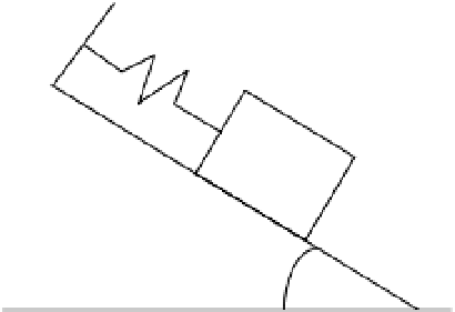
To demonstrate the process for developing a force diagram, consider the situation shown
in Figure 3-9. A box is sliding down a ramp that is at an incline angle of
q
. One end of the box is
attached to a spring that has been stretched beyond its equilibrium position. The other end of
the spring is attached to a fixed wall. The box is subject to multiple forces. The problem is to
express all of the forces mathematically and draw the resulting force diagram.
θ
Figure 3-9.
A box subject to multiple forces
Let's start with the spring, which will exert a force on both the box and the wall to which it
is attached. The magnitude of the spring force is equal to
-kDx
where
Dx
is the amount the spring
is stretched from its equilibrium position. The box is subject to the force of gravity. Gravity will
act in the vertical direction, but because the box is on the ramp, it will be useful to split the gravity
force into components that are normal and parallel to the ramp. The gravitational force on the
box normal to the ramp is equal to
mgcosq
. The ramp exerts an equal and opposite force on the box.
The gravitational force parallel to the ramp is equal to
mgsinq
. Finally, because the box is sliding,
there will be a friction force between the box and the ramp. The friction force is equal to
mF
N
where
F
N
is the normal gravitational force. A force diagram that incorporates these results is
shown in Figure 3-10.
One use for force diagrams is they make it easier to visualize and evaluate the net force on
an object. For example, looking at the force diagram shown in Figure 3-10, we can see that the
net force on the box parallel to the ramp,
F
P
, is equal to the sum of the gravitational, frictional,
and spring force components.
P
F g kx g
=
sin
θ
− Δ −
μ
cos
θ
(3.13)
The negative signs in Equation (3.13) are used to indicate that the spring and friction
forces act in the opposite direction of the gravitational force.

