Game Development Reference
In-Depth Information
airplane. Knowing that the lift force must equal the weight of the airplane, the stall speed can
be computed from Equation (10.3).
mg
v
=
(10.4)
stall
1
CA
r
2
L
,max
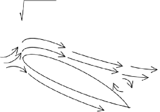
Figure 10-9.
Flow separation reduces the lift generated by an airfoil.
You will most likely want to include the possibility of stall in your flight simulation, partic-
ularly when you are modeling takeoffs and landings.
■
Tidbit
Many modern airplane wings have a row of tiny vanes called vortex generators along the top
surface of the wing. The vortex generators make it less likely that the airflow will separate over the top surface
of the wing and lower the stall speed of the airplane.
Flaps
As seen in Figure 10-10, flaps are movable sections on the aft end of the wing. They are deflected
up or down to change the lift characteristics of the wing. Specifically, flap deflection shifts the
lift coefficient curve up or down and may change the
stall angle
, the angle of attack where
the maximum lift coefficient occurs. Flaps are commonly used during takeoff and landing. In
Figure 10-10, the flap is deflected downwards, which will increase the lift coefficient of the airfoil.
Flap
Figure 10-10.
Flaps are used to alter the lift coefficient.
As an example of the effect of flaps, Figure 10-11 shows the lift coefficient profiles for the
NACA 2412 airfoil with no flap deflection and with a 20-degree downward flap deflection.
1
The
peak lift coefficient is higher and the stall angle is somewhat less when the flaps are deflected.