Game Development Reference
In-Depth Information
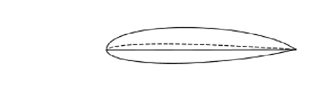
Figure 10-4.
An airfoil schematic
as shown in
Figure 10-5, is the angle the chord line makes with the velocity vector of the airfoil. As we shall
see later in this section, the lift and drag characteristics of an airfoil are often evaluated as a
function of angle of attack.
The
angle of attack
for an airfoil, typically represented by the Greek letter
α
Figure 10-5.
Angle of attack
The
incidence angle
of a wing is the angle the chord line makes with the longitudinal axis
of the airplane. Incidence angles tend to be small, usually 1 to 3 degrees. For an airplane in
straight-and-level flight, the angle of attack of the wing will be equal to its incidence angle.
How Lift Is Created
To understand how an airfoil generates lift, consider the airfoil shown in Figure 10-6. To simplify
the discussion, let's assume that the airfoil is two-dimensional, is at a fixed location, and that
air is being blown over it. Initially, the air is traveling in the x-direction only, but when the air
strikes the airfoil, it can no longer travel exclusively in the x-direction. Instead the air flow turns
and moves around the shape of the airfoil.
Chapter 3 introduced Newton's second law, which relates a force,
F
, to an acceleration
a
.
dv
Fmam
dt
==
(10.1)
Newton's second law tells us that a force is required to change a velocity. Force and velocity
are vector quantities, so a change in velocity in any direction requires a force in that direction.
Applying Newton's second law to the airfoil in Figure 10-6, the velocity direction is clearly changing
over both the top and bottom surfaces of the wing, which means that the airfoil is exerting a force