Graphics Programs Reference
In-Depth Information
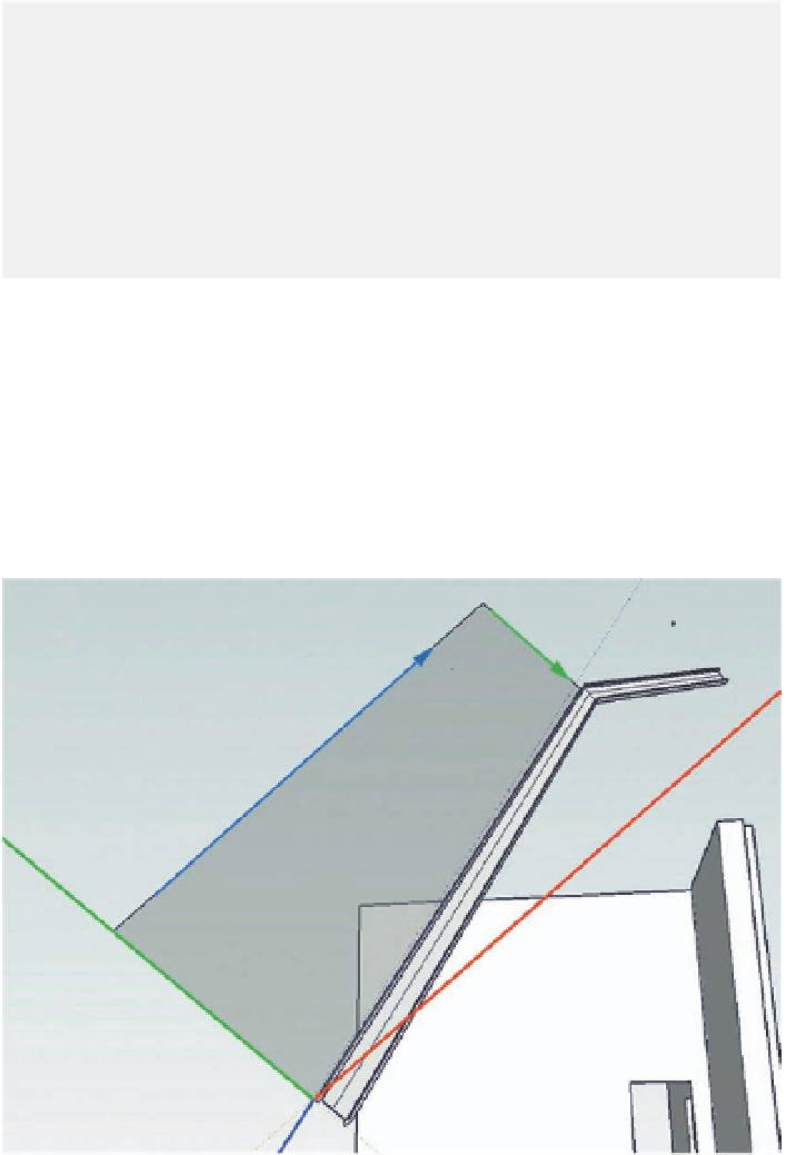
green, and blue axes were aligned with the top surface of the upper flange of
the lower part of the main girder. Use of the Axis tool, rather than the right-
click method used in stage 6, verifies that the axes are perfectly aligned with
the flange surface. The results of the right-click method can sometimes be not
quite what you are expecting. Next, a working plane was constructed perpen-
dicular to the top flange of the girder, simply by drawing in the new green and
blue axes. The same method was used to construct a working plane for the
upper part of the girder.
Tip
To move easily from one the working plane to the other, a scene was
created for each one, making sure that the Axes Position option was
checked. Now, moving from one scene to the other, the axes would always
be orthogonal to the working plane in that scene.
To avoid any inadvertent modifications to the working planes, they should
be grouped and, most importantly,
locked.
The path for the upper triangulating girder is a bit complicated: The
working plane was built on the external edge of the upper flange, but
the path for this element should start on the
internal
edge of the upper
flange. The next two clicks (where the middle strut would be built) should
be on the working plane itself. Then, the end of the line should terminate
FiG 12.7
The constructed working
plane in place: Note the position of
the axes.

Search WWH ::

Custom Search