Graphics Programs Reference
In-Depth Information
Stage 6: Modeling the Other Main Girders
Objective
: To finish the modeling of the remaining simple girders.
Data
: Model obtained in the previous stage.
Tool
: SketchUp Pro.
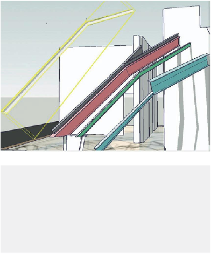
Exactly the same technique was used to model the remaining girders. In Figure
12.6, they have each been given a different color, to better distinguish them.
FiG 12.6
The four main girders
in situ.
Tip
SketchUp's bounding boxes are always created orthogonal to the
principal axes. This can make moving, rotating, and especially scaling
nonorthogonal elements rather difficult. To avoid this pitfall, before
grouping a nonorthogonal element, select one of its surfaces, right-click
on the surface, and choose Align Axes from the contextual menu. The
principal axes will now be orthogonal to that surface, so that when you
group the geometry, the bounding box will be perfectly orthogonal to it,
making it easier to manipulate (see the white girder on the left in Fig. 12.6).
Stage 7: Additional Modeling on the Main Bow Truss
Objective
: To add more details to the main girder using working planes.
Data
: Model obtained in the previous stage.
Tool
: SketchUp Pro.
To add supplementary modeling of the bow truss to the main girder, addi-
tional working planes had to be constructed. Using the Axis tool, the red,

Search WWH ::

Custom Search