Java Reference
In-Depth Information
Note that those picking behavior that are associated with important 3D objects such as
the door, oscilloscope and signal generator controls are added to the BG node or objRoot
in the code segment. On the other hand, navigation and collision detection behavior are
associated with the view platform, and are invoked through the view platform TG node or
vpTrans in the code segment.
control buttons, slIders, knobs, and other
obJects
To realize 3D instruments in the 3D world, a number of 3D visual objects for controlling
the apparatus have to be made use of. While the number of such lower level component
objects may be larger, they can often be classified as belonging to a few classes including
buttons, knobs, sliders, screens, and frames.
Although each object has its own appearance attributes, it is more convenient to define
and construct these in a standardized manner. Specifically, the following methodologies
are adopted.
1.
Each of these objects is created by specifying the vertex coordinates of the polygon
surfaces that make it up. To achieve better rendering performance, subclasses of
GeometryStripArray are used as far as possible so as to reuse as many vertices as
possible.
2.
To reduce the complexity of the model, coaxial cables, circuit board, battery, and
static clips are created using VRML format, and are loaded into the 3D virtual scene
using the vrml97 loader.
3.
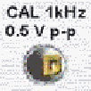
Some visual objects such as those shown in Figure 5 are realized through the use of
appropriate textures on appropriate surfaces such as an instrument panel.
Figure 5. Texture for realizing the front surface of a button test point, a test point, and a
clip


Search WWH ::

Custom Search