Biomedical Engineering Reference
In-Depth Information
Hook
Load cell
Bracket
Wire
Double interbracket distance
(A)
(B)
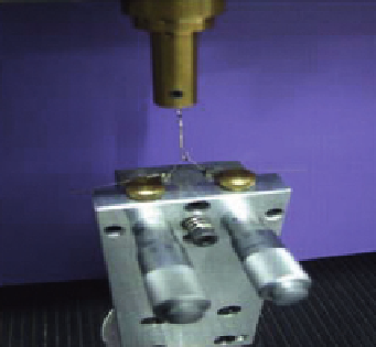
FIGURE 13.12
(A) Three-point bending test scheme; (B) a photograph of the assembling device with two brackets mounted
on its upper surface; the wire is engaged into the brackets and elevated to a given height.
Table 13.2
Summary of the Friction Measurements of Cobalt
1
IF-Coated NiTi Wires
Instantaneous
Force (N)
Static
Coefficient
Kinetic
Force (N)
Kinetic
Coefficient
Wire
NiTi uncoated (2
)
1.541
6
0.3
0.103
6
0.02
1.555
6
0.3
0.103
6
0.02
NiTi coated (2
)
1.253
6
0.2
0.083
6
0.01
1.154
6
0.2
0.077
6
0.01
Percentage of friction force
reduction (2
)
19
20
26
30
NiTi uncoated (3.8
)
1.640
6
0.2
0.109
6
0.02
1.487
6
0.2
0.099
6
0.01
Ni
Ti coated (3.8
)
1.290
0.3
0.086
0.02
0.990
0.2
0.066
0.01
6
6
6
6
Percentage of friction force
reduction (3.8
)
21
22
34
34
Ni
Ti coated (5
)
1.207
0.4
0.080
0.02
0.927
0.2
0.061
0.01
6
6
6
6
vertically positioned was slotted through the moveable bracket and connected to a load cell on one
end and to a counterweight mass of 1.5 N on the other. The friction force was measured as the
tested wire was drawn up with a constant speed of 5 mm/min while slotted in the bracket for a dis-
tance of 5 mm. The bracket was set throughout the experiment at the same position using utility
fork designed for this manner and bonded to the mobile plate using dental resin cement. In order to
simulate different levels of frictional force, the mobile plate was moved horizontally creating angu-
lations of 2
and 3.8
between the wire and the bracket. Tests were repeated 10 times for each
angle both with coated and uncoated wires. Data were obtained and analyzed using NEXYGEN
t
MT Materials Test and Data Analysis Software.
Results of the friction measurements using the Instron system are given in
Table 13.2
. Friction
measurements in 2
angle showed a reduction of 20% in the static coefficient and about 30% of the