Biomedical Engineering Reference
In-Depth Information
time when the core of the D-shaped window optical iber is exposed
to the air and inally all modes are cut off, thus allowing the maximum
etching depth and maximum etching time to be determined. In other
words, in a single mode optical iber when the transmission light is
cut off, the etching depth is 9 μm. Summarizing, the etching process
consists of the following steps:
(a) Strip off coating
(b) BOE etching
(c) Cleaning with water and drying with nitrogen
6.4.2 Polishing Method
(A)
(B)
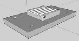
Figure 6.17
Polishing fixture diagrams: (A) V-shaped groove of the ixture,
(B) location of optical ibers in the ixture.
Optical iber windows can also be fabricated using polishing
techniques. The fabrication technique requires an appropriate
ixture (as shown in Fig. 6.17) to hold the iber. The ixture has a
groove, which is commonly V-shaped, and can be made of cut metal,
or by crystal elements shaped by anisotropic etching. The polishing
removal areas must be separated from the protected areas that are
not to be processed. Once the ixture has been attached to the iber
and placed in the polishing machine, set the high precision polishing
machine to use chemical mechanical polishing (CMP) to produce
optical iber windows. The polishing depth needs to be monitored
in real-time through the optical line monitoring system. This system
connects a iber optic light source at one end, and at the other end of
optical iber sensors measure the intensity of the light. The overall
schematic is shown in Fig. 6.18. The implementation steps are as
follows [40]:
(a) Place ibers in grooves of a substrate
(b) Fix the ibers in grooves by bonding at least a portion of each
iber on the substrate


Search WWH ::

Custom Search