Biomedical Engineering Reference
In-Depth Information
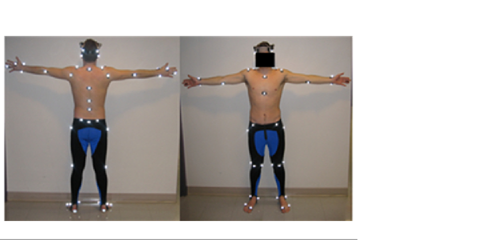
FIGURE 9.3
Marker placement schemes (T-Pose).
side-to-side and ankle rolls. Movements were designed to isolate joints or DOF in
a joint, and to identify joint limits. The knee was modeled as a single-DOF hinge
joint. Knee flexion during the ROM trial isolated this joint. However, the hip was
modeled as a 3-DOF ball-and-socket joint, so hip flexion isolated a single DOF in
the hip joint. Hip abduction and rotation were performed separately to analyze the
remaining DOF in the hip.
9.4
Methods
9.4.1
Normalizing the data
The motion capture data for the throwing task are considered in this section.
The time history of the joint angles for each subject shows variations in the
total task time, making a direct frame-by-frame comparison between the exper-
iment and prediction infeasible. Therefore, a specific normalized cycle time is
defined based on distinguishable human positions during the motion. For exam-
ple, during throwing (
Figure 9.4
), it is found that the initial cocked position
and object release point provide two comparable positions between subjects.
The throwing cycle contains all of the motion from the cocked position until
the object is released from the hand. Since the motion following the release
point
is also important, an additional 10% of data after the release point
is
also considered.
With this defined cycle, all subjects start and end in the same position inde-
pendent of the time elapsed between. In this case, the normalized time can be


Search WWH ::

Custom Search