Graphics Reference
In-Depth Information
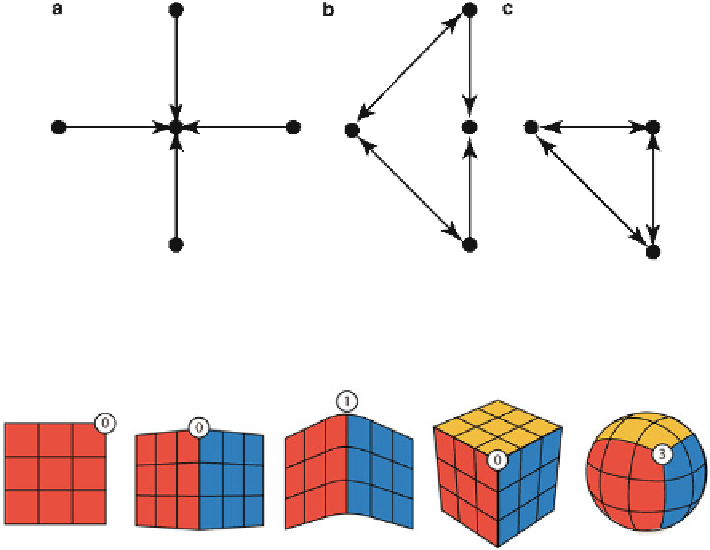
Fig. 14.15
Although node group
C
has fewer nodes and connections than groups
A
and
B,
it has
the most complex structure because each node affects both of the remaining two
Fig. 14.16
Non-tangent connections do not increase complexity, but tangent connections do, by
the number of tangent surfaces
More importantly, the intersection shape, two curves crossing at nearly right angles,
is just as much a topological characteristic of a surface as that it has four sides. This
is important to keep in mind when selecting which tool to use. The boundary of the
object is defi ned by the four-sided limit, but the shape of the object is defi ned by its
internal grid intersections. Your tools generate this grid, and each tool does it in a
slightly different way.
For instance, the revolve tool. When the revolve tool generates a surface, it
rotates a source curve around a pivot, generating a U axis isoparm based on the
formula for a circle. A loft tool, on the other hand, connects the U direction of each
of the source curves in a linear fashion, from one to the next, creating new V direc-
tion isoparms based on the position of control vertices on each of the source curves
(Fig.
14.17
). A boundary patch tool will allow the user to defi ne a surface by its
border curves alone, or the border curves combined without tangents of surfaces
that lie upon those same curves. Extrusion defi nes a surface by its internal isoparms,
and allows your application to create the boundary on its own, based on tool param-
eters and the shape of your source curves.
In addition to these surface generation types, surfaces may be modifi ed through
trimming and repositioning of control points. It can be confusing to see how many
options most applications provide in their toolboxes, but if you can remember that
Search WWH ::

Custom Search