Graphics Reference
In-Depth Information
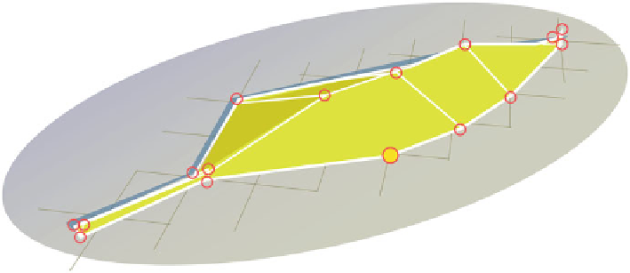
Fig. 9.13
The vertex highlighted in
yellow
is isolated because it has only two incoming edge
connections
9.3.7
Isolated Vertices
Any vertex that has no more than two incoming edge connections is an isolated
vertex (Fig.
9.13
). They can be created in many ways. All major applications have
tools built to fi nd and eliminate these remnants of the modeling process, but some-
times the best method is to simply select them and delete.
If you use the select and delete solution, be careful to avoid selecting corners of
quad polygons because these are technically isolated vertices but they are necessary
for that shape.
9.3.8
Lamina Faces
When two or more faces share all of the same edges, a
lamina face
is created. This
is different from coincident vertices (Sect.
9.4.3
) because with lamina faces there
usually are no coincident vertices, despite the presence of more than one face
between whatever vertices are present. These can be made by merging the vertices
of two or more coincident faces.
The best clue that a lamina face is present is if, in shaded mode, a
fl ickering
is
noted when rotating the camera around the face (Fig.
9.14
). If this is present, or if
the shading on the face appears wrong, you should do a face count to determine how
many faces are present. If there are more than one but there should be only one, you
have either lamina or coincident faces. Perform a vertex count to determine if they
are lamina or coincident faces. If the vertex count is too low for the number of faces,
then you have at least some lamina faces. Another test is to display the normals for
the object. Sometimes you will see normals pointing in opposite directions on what
appears to be the same face.
Search WWH ::

Custom Search