Graphics Reference
In-Depth Information
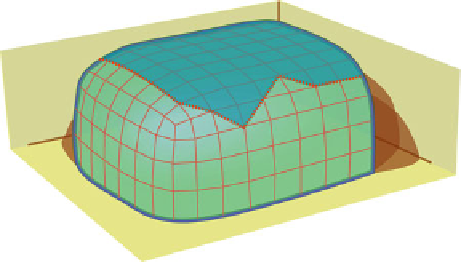
Fig. 9.4
In this object, the
dotted red line
represents an irregular texture boundary. Unless the
object requires a jagged edge for a specifi c reason, boundaries should follow the structure of the
object they represent
It is possible to correct this mistake by painting the texture maps to hide the
incorrect texture boundaries, but this only works if the materials involved are of the
same type. If they are different, even if the textures are in the correct place, the faces
on either side of the boundary will refl ect light differently and expose the problem
(Fig.
9.4
).
This happens when an inexperienced artist, concerned only with the overall
shape of an object, disregards logical internal boundaries within an object.
9.2.4
Open Corners After Extrude
Some tools do not automatically clean up after themselves. Extrusion operations,
when performed on separate faces, will create gaps between the extruded faces
(Fig.
9.5
). This is especially apparent with acute angles, such as the corners of a
cube. Some applications allow faces to be extruded together in multiple directions
at once without breaking connections between extruded faces. This is the best way
to make a corner extrusion, but if your application doesn't have this option, you will
have to manually edit the corners after you have made your extrusions. If you don't
fi x the corner, it can be a serious likeness error, depending on how prominent the
corner is. It would also be an optimization error because there will be unnecessary
vertices and faces in this portion of the model.
9.2.5
Smoothing Incorrect
Smoothing
, in the context of shading, refers to the way light reacts to the elements
of your model. As described in Sect.
2.4.1.5
,
all elements of a model have normals.
The normals are used as part of a calculation that determines at what angle light rays
Search WWH ::

Custom Search