Biomedical Engineering Reference
In-Depth Information
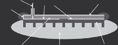
Dielectric substrate
Polymethyl methacrylate walls
Conductor
Feed
Patch
Ground plane
FIGURE 4.13
Schematic view of a microstrip transmission line (left)
and a microstrip rectangular patch antenna (right). In both cases a
dielectric substrate (thickness
t
and relative permittivity ε) separates a
ground plane and appropriately shaped conductors.
Polyvinyl chloride cone
FIGURE 4.12
Schematic drawing of lucite cone applicator (van
Rhoon et al. 1998). The side walls of the horn section consist of polyme-
thyl methacrylate sheet, and a PVC cone is located in the horn section
at the center of the applicator's aperture.
RF feed
Ground plane
Active electrodes
Short circuit
of dimensions for the PVC cone lead to a threefold increase in
EFS compared to a conventional metallic walled-horn appli-
cator of the same dimensions (van Rhoon et al., 1998), and
this advantage has also been demonstrated in clinical studies
(Rietveld et al. 1999).
Although waveguide-based applicators are generally very
useful for delivering superficial hyperthermia, their bulk
sometimes makes access to the tumor site difficult. A means
of overcoming this problem is to use an applicator based on
a microstrip transmission line. A microstrip transmission
line consists of a conducting strip separated from a ground
plane by a thin dielectric substrate. The line does not support
a true transverse electromagnetic (TEM) wave but a set of dis-
crete hybrid modes with non-zero
E
z
and
H
z
components (t he
z direction being along the transmission line). However, the
longitudinal components are small, and so the lowest order
mode resembles a TEM wave at low frequency. This mode is
often known as a quasi-TEM wave. Methods for determining
the propagation characteristics of microstrip lines are dis-
cussed by James et al. (1985).
A simple microstrip antenna may consist of a rectangular
metallic patch with dimensions equal to approximately half
the propagation wavelength (Figure 4.13). However, the char-
acteristics of such an antenna are sensitive to the dielectric
properties of the media close to it, and so practical designs
must be such as to minimize the dependence of performance
on changes in loading. In practice the provision of a water
bolus approximately 3 cm thick should result in a resonant
frequency that does not vary significantly with load and that
avoids exposing tissue to the relatively large normal electric
field components present at the edges of the patch (Underwood
et al. 1992).
In addition to devices based on a rectangular patch, microstrip
applicators of different geometry have also been investigated.
For example, Archimedean spiral antennas provide a circularly
polarized electric field and a wider bandwidth than rectangular
Substrate
Water bolus
Silicon body
FIGURE 4.14
Schematic diagram showing cross section of a contact
flexible microstrip applicator. (After Gelvich, E.A., and Mazokhin, V.N.
IEEE Trans. Biomed. Eng.
49, 2002.)
or circular patches (Samulski et al. 1990; Jacobsen et al. 2000,
2005).
A type of device that offers flexibility and is lightweight is
the contact flexible microstrip applicator (CFMA; Gelvich and
Mazokhin 2002). As indicated in Figure 4.14, the CFMA is based
on a microstrip structure consisting of two coplanar active elec-
trodes and a ground plane incorporated in a semirigid silicon
frame. In use, a thin silicon bolus is filled with circulating dis-
tilled water to improve impedance matching as well as to cool
superficial tissues. Collapse of the bolus is prevented by the pres-
ence of silicon lugs up to 5 mm high.
4.8.3 arrays of applicators
The use of a single-heating device when heating superficial tissues
is limited in most cases since the distribution of absorbed power
cannot be changed in a predictable manner, and only the power
delivered to the tissues and the position of the device relative to
the patient can be adjusted during treatment. The use of an array
of devices in which the power delivered to individual devices can
be controlled should offer an improvement. Furthermore, the
array of devices can be driven either incoherently or coherently.
In the former case the power fed to each device may be controlled,
and the resultant SAR distributions from each device are simply
added. In the latter case, the E-fields produced by each device
are added, and the total E-field produced depends upon both the
amplitude and relative phase with which each device is driven;