Biomedical Engineering Reference
In-Depth Information
Q
Q
1
Q
2
J
1
J
2
J
1
J
2
E
b
1
E
b
2
E
b
1
E
b
2
1 -
ε
1
1
1 -
ε
2
1 -
ε
1
1 -
ε
2
ε
1
A
1
A
1
F
1 2
ε
1
A
2
A
1
F
1 2
ε
1
A
1
ε
2
A
2
1
1
A
2
F
2 3
A
1
F
1 3
FIGURE 1.12
Electrical resistance model for the radiation exchange
between two surfaces with a shape factor
F
1→2
.
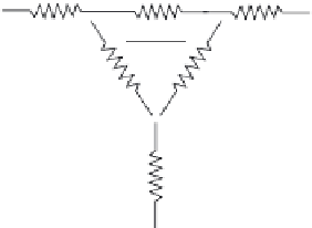
FIGURE 1.14
Electrical resistance model for the radiation exchange
among the surfaces of a three-bodied system in which surface 3 is per-
fectly insulated.
These two types of resistance elements can be applied to model
the steady state interactions among systems of radiating bod-
ies. The simplest example is of two opaque bodies that exchange
radiation only with each other. This problem is characterized by
the network shown in Figure 1.12.
This network can be solved to determine the radiation heat
flow in terms of the temperatures (
T
1
,
T
2
), surface properties (ε
1
, ε
2
),
and system geometry (
A
1
,
A
2
,
F
1→2
):
The radiation heat flow for this system is written as a function
of the system properties, with the shape factor reciprocity rela-
tion applied for
A
1
F
1→2
=
A
2
F
2→1
, as
(
)
AT T
AA AF
AAF
σ
4
−
4
11
2
Q
=
.
12
→
1
+
+−
2
A
A
1
(1.92)
1
2
11 2
→
1
2
−
1
+
−
1
2
ε
−
(
)
ε
1
2
1
12
→
2
(
)
4
4
EE
−
σ−
TT
b
1
b
2
1
2
Q
=
=
.
A final case to be discussed addresses the effect of an absorb-
ing and transmitting medium included in a radiating system.
Glasses and gases are examples of this type of media. If the
medium is nonreflective, then
12
→
1
−ε
ε
1
1
−ε
1
−ε
ε
1
1
−ε
1
2
1
2
+
+
+
+
(1.91)
AAF
ε
A
AAF
ε
A
11
11 2
→
22
11
11 2
→
22
Note that the second term in this equation has a linear dif-
ferential in the driving potential, whereas the third term has a
fourth power differential. A major advantage of the electrical
circuit analogy is that a radiation problem can be expressed
as a simple linear network, as compared to the thermal for-
mulation in which temperature must be raised to the fourth
power.
Given the network modeling tools, it becomes straightfor-
ward to describe radiation exchange among the components of
an
n
-bodied system. A three-bodied system can be used to illus-
trate this analysis as shown in Figure 1.13.
In this system each of the three bodies experiences a unique
radiant heat flow. For the special case in which one surface, such
as 3, is perfectly insulated, meaning that all incident radiation is
reradiated, then the diagram is simplified to a combined series/
parallel exchange between surfaces 1 and 2 as seen in Figure 1.14.
α+τ=ε+τ=
(1.93)
1.
mm mm
Radiation that is absorbed by the medium is transmitted and
then emitted to its environment. For a system consisting of two
surfaces 1 and 2 that see only each other, plus an intervening
medium
m
, the net energy leaving surface 1 that is transmitted
through the medium and arrives at surface 2 is
JAF
1112
τ
.
→
m
Likewise, the energy flow in the opposite direction is
JAF
222
τ
.
→
m
The net interchange between surfaces 1 and 2 via transmission
through the medium is then the sum of these two flows.
JJ
AF
−
1
2
QJ
=τ −τ =
AF
J
F
(1.94)
Q
1
Q
2
12
→
1
m
1
12
→
2
m
2
→
1
1/
(1
−ε
)
J
1
J
2
11 2
→
m
E
b
1
E
b
2
1 -
ε
1
1
1 -
ε
2
The effect of the medium can be represented by a radiation
network element in Figure 1.15.
A
1
F
1 2
ε
1
A
1
ε
1
A
2
1
1
A
1
F
1 3
A
2
F
2 3
J
3
Q
1 -
ε
3
J
1
J
2
Q
3
ε
3
A
3
1
A
1
F
1
→
2
(1 -
ε
m
)
E
b
3
FIGURE 1.15
Electrical resistance model for the effect of an absorb-
ing and transmitting medium on the thermal radiation between two
surfaces.
FIGURE 1.13
Electrical resistance model for the radiation exchange
among the surfaces of a three-bodied system.