Biomedical Engineering Reference
In-Depth Information
2
0.014
3.5
0.016
0.014
0.012
0.01
0.008
0.006
0.004
0.002
0
1.8
0.012
3
1.6
1.4
1.2
1
0.8
0.6
0.4
0.2
0
50
0.01
2.5
0.008
2
0.006
1.5
0.004
1
SAR
Susceptibility
SAR
Susceptibility
0.5
0
246810 12
Applied field strength (kA/m)
0.002
0
100 150 200 250 300
Applied frequency (kHz)
350 400 450 500
14
16
18
20
FIGURE 17.5
Effects of frequency (a) and field strength (b) on magnetic fluid susceptibility and SAR. Field fixed at 10 kA/m (a) or 250 kHz (b).
and relaxation behavior, but the impact is not significant within
the temperature ranges relevant to biological heating.
The previous description assumes uniformly dispersed, non-
interacting particles. Interparticle interactions will considerably
increase the complexity of the problem, but can be represented
as a system of interacting dipoles. This problem has not been
thoroughly addressed in literature, but is very relevant, as par-
ticles often will form tight aggregates in vivo, affecting their
collective magnetic behavior. Contradicting effects have been
shown in literature, with aggregation leading to both reported
increases (Dennis et al. 2009) and decreases (Jordan et al. 1996)
in heating effects for different nanoparticle systems. Thus inter-
particle interactions may provide another potential dimension
of engineering analysis for optimizing heating.
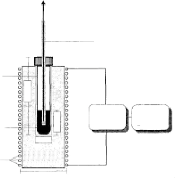
17.2.4 alternating Magnetic Field Generation
There are many different means of creating magnetic fields, but a
great majority of developmental work is performed with fields cre-
ated by inductive coils, due to the ease of application and high field
uniformity within the coil. Basic characterization of heating for fer-
rofluid samples is often performed in experimental setups similar
to that illustrated in Figure 17.6. The strength of the uniform field
within the coil can be theoretically estimated by (O'Handley 2000):
NI
L
H
=
(17.16)
a
where
N
is the number of turns in the coil,
I
is the coil current,
and
L
is the coil height, but this will typically overestimate the
ermometry probe
Sample tube
HP-
generator
Matching
network
Ferrofluid sample
12 mm
Styrofoam
insulation
Coil term
Coil diameter: 50 mm
FIGURE 17.6
Inductive coil-based experimental setup for SAR characterization. (From Jordan, A. et al.,
International Journal of Hyperthermia
25, 7, 1993.)