Biomedical Engineering Reference
In-Depth Information
Transducer geometry plays an important role in successful
device design. Small aperture arrays suffer from weak focus-
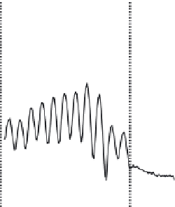
ing ability, especially in the axial direction. Not only does this
increase focal spot size, but it increases the risk of standing
wave formation in the skull cavity, especially at low frequen-
cies (Figure 14.3). High focal number (FN) transducers produce
almost planar ultrasound conditions in the pre- and post-focal
regions, creating ideal conditions for standing waves at bone
interfaces (Baron et al., 2009). Small aperture transducers also
increase skull heating by concentrating the delivered energy
through a small area of the skull. The adopted approach to mini-
mize skull heating is to use a large aperture transducer, which
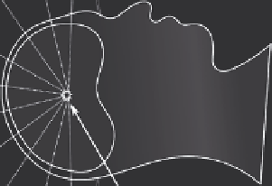
can produce large focal gains [Sun and Hynynen, 1998]. Clement
et al. [2000] conducted the first experiments using a hemispheri-
cal transducer for transcranial surgery (Figure 14.4). This first
transducer consisted of 64 elements operating at 0.7 MHz and
14.2.4 System Design for transcranial
Ultrasound therapy
Transducer and system design are important elements of
transcranial therapy. Compromises are necessary in order to
produce a functional system. For example, low frequencies
are desirable to minimize attenuation and distortion effects.
However, low frequencies also increase the risk of standing
waves [Azuma et al., 2004] and reduce the cavitation thresh-
old in tissue [Hynynen, 1991], both of which have strong safety
implications. Low frequencies also increase focal spot size, but
above 1 MHz skull heating becomes an issue and prevents effec-
tive thermal ablation unless cavitation-enhanced methods are
used [Sun and Hynynen, 1998]. At this time, the highest fre-
quency prototype device for transcranial FUS operates at 1 MHz
[Aubry et al., 2010].
Profile in water
Profile in rat skull
1
Top of skull
Bottom of skull
0.5
f
= 0.841, FN=1
5 cm aperture
0
-10
Prefocal
0
10
-10
0
10
Postfocal
Axial distance from focus (mm)
FIGURE 14.3
Axial pressure profile in an
ex vivo
rat skull of an FN 1 transducer operating at 0.841 MHz. (Based on data from O'Reilly, M.A., Y.
Huang, and K. Hynynen,
Phys Med Biol
55, 2010.)
Circulating water
Ta rgeting/phase
calculation
PC
Multi-channel
power amplifier
MRI images
Focus
Larger aperture
tranducer array
MRI bore
FIGURE 14.4
Illustration of transcranial therapy using a hemispherical array.