Biomedical Engineering Reference
In-Depth Information
14.2 Focused Ultrasound in the Brain
2004], causing undesired heating and unpredictable
in situ
pres-
sures. Several techniques have been employed to overcome these
challenges.
14.2.1 Ultrasound and the Skull Bone
The greatest obstacle for the use of focused ultrasound in the
brain is the skull bone. First, a large acoustic impedance mis-
match occurs at bone/tissue interfaces, resulting in high reflec-
tion losses that increase with incidence angle (3 to 15 dB at
normal incidence [Fry and Barger, 1978]). At low frequencies,
below 500 kHz, reflection losses dominate overall signal loss
through human skull bone, while at higher frequencies attenua-
tion (absorption + scattering) losses also contribute significantly,
resulting in very poor transmission at frequencies above 1 MHz
[Fry and Barger, 1978]. Attenuation increases with increasing
frequency as the wavelength of the ultrasound becomes small
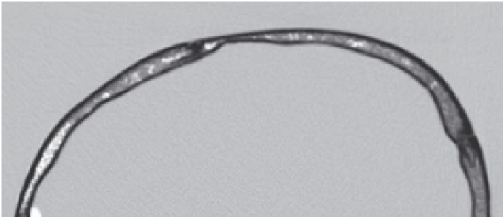
relative to the thickness of the bone. Skull bone has an outer
dense cortical layer surrounding a layer of porous trabecular
bone (Figure 14.1).
The skull has irregular surfaces, and varying thickness and
density. The speed of sound in skull bone depends on its density
[Clement et al., 2002] and thus varies across the bone thickness
and from location to location, but is on average 2900 m/s [Fry
and Barger, 1978; Pichardo et al., 2011], double that in water.
The result is that sound passing through the cranium undergoes
location-specific phase delays resulting in distortion of the focus.
At low frequencies the focal distortion is less severe due to
the long wavelength, but increases greatly with frequency. In
the late 1990s, Hynynen and Jolesz demonstrated that a sharp
focus could be produced through human skull below 0.5 MHz,
while above 1 MHz phase correction using a multi-element array
was required to eliminate field distortions [Hynynen and Jolesz,
1998]. However, even at low frequencies, skull heating remains a
problem, as skull bone absorbs energy at a higher rate than soft
tissues. Therefore, the potential exists for the temperature rise
in the skull to approach or surpass the temperature rise at the
transducer focus [Connor and Hynynen, 2004].
Finally, the long sonations associated with therapeutic ultra-
sound and the presence of highly reflective bone surfaces can
give rise to standing waves in the skull cavity [Azuma et al., 2004;
Baron et al., 2009] and within the bone [Connor and Hynynen,
14.2.2 the Skull Window approach
The first ultrasound treatments in the brain were performed
through a craniotomy window. This approach allows a sharp
focus to be achieved in the brain without concerns for skull
heating, and was for many years the only method to conduct
ultrasound brain therapy in clinical trials [Fry and Fry, 1960;
Heimburger, 1985; Guthkelch et al., 1991]. The bone could be
replaced by a material with better acoustic properties to best
transmit the ultrasound energy [Tobias et al., 1987]. By removing
the skull bone, focusing can be achieved with a single-element
spherically focused transducer, minimizing hardware and
software requirements. However, the skull window approach is
invasive and limits treatment to the area exposed by the acoustic
window. A superior approach is to focus through the skull bone.
14.2.3 Focusing through the Skull
Focusing through the skull can be achieved using multi-element
arrays with applied phase delays and amplitude modulation to
compensate for skull effects. There are several techniques for
calculating the array element driving signals. The simplest
method requires a hydrophone to be placed at desired focus
to record the signals from each array element turned on in
sequence [Smith et al., 1977; Thomas and Fink, 1996; Hynynen
and Jolesz, 1998; Clement et al., 2000]. The deviations in phase
and amplitude from the expected are measured by the hydro-
phone and can then be compensated for by adjusting the
RF-driving signals of the transmit elements to negate the effects
of the skull (Figure 14.2).
Similarly, a source can be placed at the focus and the emis-
sions captured by the transmit elements. Using a time-reversal
mirror, a sharp focus can be achieved and amplitude correction
can also be applied [Fink, 1992; Thomas and Fink, 1996]. Time-
reversal mirrors allow adjustment of amplitude and phase at the
Cortical bone
Cortical bone
Trabecular
bone
FIGURE 14.1
CT image of an
ex vivo
human cranium showing internal structures.