Biomedical Engineering Reference
In-Depth Information
(a)
(b)
(c)
(d)
(e)
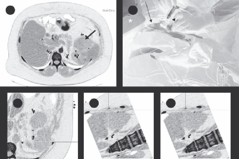
FIGURE 12.7
Electromagnetic tracking to guide renal tumor RFA. (a) Preprocedure contrast-enhanced axial CT demonstrates a left upper renal
neoplasm. (b) Fiducial markers (long white arrow) on the patient's skin surface enable registration of electromagnetic tracking with those on cor-
responding CT images. (c-e) Real-time 3-dimensional visualization and navigation during RFA is made possible by tracking the tip of the guiding
instrument using tiny sensors embedded in the electrode guide. Images from the graphic user interface demonstrating coregistered data, enabling
real-time display of instrument position and orientation. The crosshairs generated by electromagnetic needle tracking are fused with multiplanar
reconstructed CT images. (Reprinted from Stone, M. J., Venkatesan, A. M., Locklin, J. et al.,
Tech Vasc Interv Radiol
10, 2, 2007. © 2011, with per-
mission from Elsevier.)
was tracked by an infrared camera was used to navigate and
guide the needle percutaneously to the target. A mean decrease
in fluoroscopy duration of 18 seconds was noted for each probe
placed. The mean target registration error was 4.2 mm, and no
complications were observed.
In a porcine model, this same group investigated the addition
of real-time ultrasonography to CT imaging for perctuaneous
renal cyroablation (Haber et al. 2010a). Thirty-five artificial renal
tumors were created in 11 pigs. The cyroprobe was inserted per-
cutaneously and ice ball formation was monitored continuously
using real-time sonography. Synchronization between the ultra-
sound and CT images was successful in all cases.
MRI can also be used to monitor cyroablation and has the
advantage of better soft tissue contrast. MRI-guided percutane-
ous cyroablation of liver cancer was completed in 32 patients
with hepatocellular carcinoma at the diaphragm dome, the
first hepatic hilum, and near the gallbladder (Wu et al. 2010).
Cryoprobe insertion was guided by an optical navigation sys-
tem (Panasee
•
MRI-compatible optical navigation system,
XinAoMDT, China) and with continuous MRI scans (Signa
•
0.35T open scanner, GEHealthcare, Milwaukee, U.S.). The num-
ber of cryoprobes used varied from 2 to 7. The conclusions were
that 3D imaging, an arbitrary oblique scan plane, direct multi-
plane reconstruction, and fusion with optical navigation infor-
mation allowed for faster, safer, and more precise probe position.
Intraoperative visualization of 3D temperature maps along
with 3D navigation for hepatic cyroablation was studied in
a porcine model (Samset et al. 2005). An optical tracking sys-
tem was integrated with a navigation system and graphical user
interface based on the Qt application programming interface
(Nokia, Finland). The software included the ability to segment
the liver and display temperature maps (Figure 12.10). The con-
cept was demonstrated in a single swine study, but no validation
was completed.
An early paper described image navigation for MR-guided
cryosurgery in 11 cases including five renal tumors, three uterine
(a)
(b)
Tumor
Needle
Portal vein
Probe
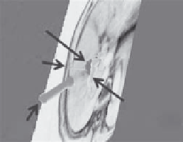
FIGURE 12.8
Navigation display based on the 3D Slicer user interface
show the ultrasound probe, needle, tumor, and portal vein (a) and seg-
mentation of the gall bladder displayed with the tumor (b). (Reprinted
from Maeda, T., Hong, J., Konishi, K. et al.,
Surg Endosc
23,5, 2009. ©
2011, with permission from Springer Science + Business Media.)