Biomedical Engineering Reference
In-Depth Information
(a)
(b)
(c)
(d)
FIGURE 10.1
The main components of the ExAbalte 2000 system: (a) the operator console, (b) the equipment cabinet, (c) the patient treatment
table, and (d) the chiller.
ExAblate 2000 can be integrated as an add-on to a 1.5 or 3.0
Tesla MR Scanner from GE Medical Systems. The ExAblate 2000
received the CE mark in 2002 and FDA clearance in 2004 for the
treatment of symptomatic uterine fibroids. In 2007, it received
the CE mark for pain palliation of bone metastases, and in 2010
for adenomyosis. This device has already treated thousands of
patients around the world and is currently being investigated in
clinical trials for painful bone metastases (phase III), breast can-
cer (phase I), liver cancer (phase I), and prostate cancer (phase I).
electronic steering). However, since the transducer is a phased
array, the phases of the radiofrequency signals to each array ele-
ment can be adjusted to steer the acoustic focal length from 6 cm
to 22 cm from the transducer's center.
The size of the focal zone
(lesions) may vary depending on the size and depth of the vol-
ume being treated, ranging from 1 mm to 10 mm in diameter
and from 8 mm to 45 mm in length. The operating frequency is
around 1 MHz, ranging from 0.95 to 1.35 MHz. For bone treat-
ments the frequency used is 1 MHz.
10.2.1.1.2 Equipment Cabinet
The equipment cabinet is located in an adjacent control room.
It consists of a main power switch and the electrical components
that drive the transducer's positioning system and the ultra-
sound phased array.
10.2.1.1 Main Components
The main components of the system include the patient treatment
table containing the ultrasonic array and integrated with the MR
scanner (GE 1.5 T or 3.0 T), the operator console, the equipment
cabinet, and the chiller (Figure 10.1a-d). The safety devices are
also installed in the clinical focused ultrasound system.
10.2.1.1.3 Operator Console
The console is located in the control room next to the GE SIGNA
workstation. It includes a flat panel display, keyboard, mouse,
and stop-sonication button. It controls the entire treatment pro-
cess including treatment planning, the treatment table position,
the transducer's position and tilt angle, sonication power and
time, and MRI monitoring and assessment of the treatment. The
latter includes both conventional MR imaging sequences and
MR temperature mapping estimation sequences.
10.2.1.1.1 Patient Treatment Table
The patient treatment table is a modified GE SIGNA MRI table.
It is detachable and
can be docked to a GE 1.5 T or 3.0 T MR
scanner in the same way that the standard MR table docks; it is
connected with a single quick-connect socket. A phased array
spherically curved transducer with 208 elements (Figure 10.2) is
housed in a sealed degassed water tank in the patient treatment
table and is connected to an electronic motioning and position-
ing system controlled by a computer. The transducer can be
moved in the X and Y directions (along and horizontally across
the scanner's longitudinal axis, respectively) but not in the Z
direction (vertically up and down); the transducer can also be
tilted. The geometric focal length of the array is 16 cm (without
10.2.1.1.4 Chiller
A cooling system rack, which includes the chiller and associated
electronics, is also installed in the equipment room. It is used for
cooling the water in the tank and also for breast treatments to
prevent skin burns produced by ultrasound absorption.
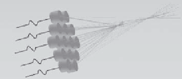
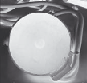
208-element
phased array
transducer
FIGURE 10.2
The phased array transducer. (Courtesy of InsighTec, Inc.)