Biomedical Engineering Reference
In-Depth Information
be included via other ways (e.g., by explicitly including these ves-
sels in the model geometry). Whether tissue is destroyed due to
heating depends on both temperature and time (see Chapter 2,
this topic). As an approximation, a few minutes are necessary to
kill cells at 50°C, but only seconds at temperatures above 60°C
(Dewhirst 2003). While there are some differences in thermal
tolerance between cell types, these differences are not relevant
for thermal ablation procedures due to the large temperature
gradients. Since thermal ablation procedures happen in a time
frame of several minutes, the 50°C isotherm is frequently used
to approximate the ablation zone boundary (boundary of cell
death; see Figure 9.2) (Berjano 2006).
During RF ablation, maximum tissue temperatures up to
~110°C can be achieved. Above this temperature, tissue vapor-
izes and prevents any further heating by RF current due to the
electrically insulating properties of the vapor. In addition, there
is the possibility of tissue carbonization (often referred to as “tis-
sue charring”) at locations of very high RF current densities—
typically very close to the RF electrode. Tissue charring is an
irreversible process and limits further RF energy deposition. The
applied RF power therefore has to be controlled to keep tissue
temperature in the desired range and limit both vaporization
and charring.
Most commercial RF ablation devices employ one of the fol-
lowing three methods of controlling magnitude of applied RF
power:
Ta rget
tissue
RF electrode
RF generator
Ground pad
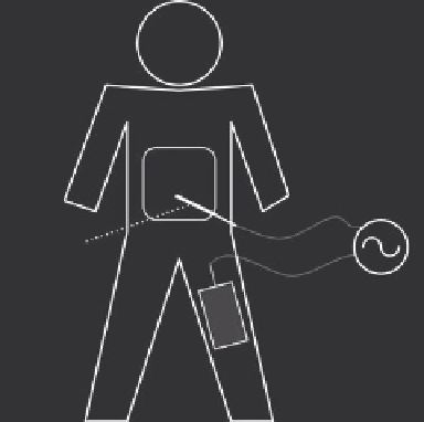
FIGURE 9.1
Overview of an RF ablation procedure. A RF electrode
is inserted into the target tissue under imaging guidance. RF energy
provided by a generator is applied to the electrode and results in tis-
sue heating around the electrode. A ground pad placed on the patient's
thighs or back serves as return path for the RF current. (Reproduced
with permission from S. Vaezy and V. Zderic, eds.
Image-Guided
herapy Systems
, Artech House, Inc., Norwood, MA, 2009. © 2009 by
Artech House, Inc.)
applicators, the SAR depends on electrical tissue conductivity
and magnitude of electric current density generated around the
electrode (Equation 9.1).
Te mperature
100°C
1 cm
σ
ρ
1
2
2
SARE
=
||
=
||
J
(9.1)
σ ρ
×
(σ = tissue electrical conductivity; ρ = tissue mass density;
E
=
electric field strength;
J
= electric current density).
The process of tissue heating during RF ablation can be math-
ematically described by the following heat transfer equation
where
T
represents spatially and temporally varying tissue tem-
perature (Diller 2000):
∂
∂
T
t
E
2
(9.2)
37°C
ρ
c
=∇⋅∇+−
kT
Q
pref
σ
(
k
= tissue thermal conductivity;
c
= tissue specific heat;
T
= tis-
sue temperature).
The term on the left-hand side represents the change in tissue
temperature due to RF heating. The first term on the right-hand
side describes thermal conduction, and the second term repre-
sents heat generated by RF current (equivalent to SAR). The term
Q
perf
represents heat losses due to cooling by blood perfusion. A
number of ways have been suggested to mathematically model
perfusion, and the most widely used model employs a distrib-
uted heat sink and was first proposed by Pennes more than 50
years ago (Pennes 1948), but is accurate only for tissue regions
where small vessels (<1 mm) are present. Larger vessels have to
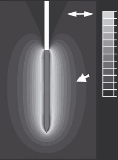
FIGURE 9.2
Tissue temperature profile at the end of a 12 min RF
tumor ablation with a cooled needle electrode (same as shown in Figure
9.6B) from a computer simulation. The black part of the electrode is
electrically insulated, and heating due to RF current results around the
exposed metal electrode (electrode tip, shown in gray). Black arrowhead
marks boundary of ablation zone (~50°C).