Biomedical Engineering Reference
In-Depth Information
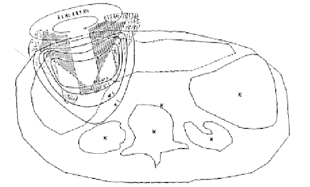
FIGURE 6.8
Early example of treatment planning for hyperthermia with a single mechanically scanned ultrasound transducer. The isotherms
are represented by contours, the focused pressure beams are the shaded regions, and both of these are overlaid on contours that represent bone and
tissue structures. (After P. P. Lele and J. Goddard,
Proc. 9th IEEE EMBS Conf.
, IEEE, New York, 1987.)
pressure at a specified point in space, where the phase of the cal-
culated pressure is evaluated relative to the phase of the input
signal. The relative phase of the pressure at this field point is cal-
culated for each element, and when the phase of the sinusoidal
driving signal applied to each element is defined as the negative
of each relative phase value, a focused pressure field is generated.
The phase of each excitation signal, which is also the phase of the
conjugated pressure field produced by each array element at
the focal point, maximizes the constructive interference in this
location. This single focus beamforming approach is applicable
to any phased array geometry.
A single focus generated by an ultrasound phased array is
much smaller than the tumor target, so electronic scanning
or some other method is required to improve tumor cover-
age. One such approach involves single spot scanning, which
focuses ultrasonic energy at discrete points within the tumor
volume. Single spot scanning is relatively straightforward in
terms of driving signal calculations and other implementation
details, but spot scanning is also potentially limited by interven-
ing tissue heating (Sleefe and Lele 1985), which is increasingly
problematic for larger tumors and/or smaller array apertures
(Wang et al. 1994). With single spot scanning, intervening tissue
heating is caused by overlapping power contributions from the
individual focused beams, which is effectively the same prob-
lem that causes pre-focal heating with mechanically scanned
ultrasound applicators. Whereas mechanical scanning reduces
problems with intervening tissue heating by turning off the
transducer that is closest to the central axis, ultrasound phased
arrays achieve similar results by cancelling axial pressure fields.
This approach, which is enabled through electronic control of
the driving phases and amplitudes transmitted to each array ele-
ment, prevents ultrasonic energy from preferentially accumulat-
ing along the central axis.
The annular patterns produced by the sector-vortex array
(Cain and Umemura 1986) are examples of focal patterns that
broaden the focal pattern while cancelling the on-axis pressures.
The annular patterns generated by the sector-vortex array are
obtained by adding a constant phase increment to the driving
signal for each element in a ring, where the phase offset defined
for one revolution around a ring of elements is an integer mul-
tiple
M
of 2π radians. The resulting pressure distribution in the
focal plane produced by a single ring of elements is approxi-
mately represented by a Bessel function of order
M
. When
M
= 0, the sector-vortex array generates a single axial focus. For
integer
M
> 0, annular patterns that cancel the on-axis pressure
fields are produced, where increasing the value of
M
increases
the radius of the annular pattern generated by a single ring of
elements.
Relative to a single focal spot, multiple focus patterns also
increase the size of the heated volume, and some of these pat-
terns cancel the on-axis pressures simultaneously. One multi-
ple focusing method evaluates the transfer matrix between the
array elements and the focal points (and nulls) and computes
the minimum norm pseudo-inverse of this matrix to deter-
mine the phased array driving signals (Ebbini and Cain 1989).
The pseudo-inverse method, when combined with an iterative
weighting algorithm, improves the excitation efficiency of the
array so that the amplitudes of the excitations applied to each
element are approximately equal. An extension of the pseudo-
inverse method defines an objective function to maximize the
intensity gain of the focal pattern generated by the phased array
(Ebbini and Cain 1991). By maximizing the intensity gain, the
heat localization is improved and problems with intervening tis-
sue heating are reduced. Examples of gain-maximized multiple
focus intensity patterns are shown in Figure 6.9. A further reduc-
tion in axial heating is achieved with mode scanning (McGough
et al. 1994), which produces symmetric multiple focus patterns
that simultaneously cancel the on-axis pressure field. Mode scan-
ning exploits the planar symmetry in most phased array struc-
tures to produce rotating pressure fields similar to the annular