Biomedical Engineering Reference
In-Depth Information
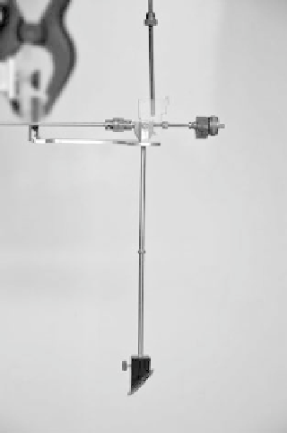
The example shown in Figure 5.11 comprises a vertical rod sus-
pended from a horizontal bar with adjustable counterbalance. At
the lower end of the rod is a flat plate, onto which the focus of a
HIFU device can be directed under free field conditions within a
tank of water. This plate is typically at 45 degrees to the direction of
propagation of the acoustic field to avoid the generation of standing
waves between it and the transducer through multiple reflections
of the beam. The force on the plate causes the rod to tilt. Moveable
weights on the horizontal arm allow the user to counteract this force
by increasing the opposing moment on the rod. By measuring the
distance the weight is moved to bring the rod back to a vertical posi-
tion during the exposure, the force on the plate resulting from the
pressure of the acoustic field can be calculated. A number of alter-
native devices have been developed, based on concepts that are less
user dependent and appropriate for unfocused or weakly focused
transducers, such as are used for physiotherapy. For example, it is
possible to measure the effective weight of an enclosed absorbing
oil bath using digital scales when an acoustic field is incident from
above (Sutton et al. 2003). This is directly related to the incident
radiation force, and therefore the output power, of the transducer.
Another example uses an electromagnet to oppose the force of
an acoustic field on a sensitive balanced cone of metal. A current
is induced in a coil of wire to oppose the motion of the cone, and
the resulting voltage is measured and calibrated for acoustic power
(Perkins 1989). A solid state device has also been developed, which
relies on rapid calculation of the rate of change of temperature of an
absorbing material (Zeqiri and Barrie 2008). From physiotherapy
transducer power measurements, intensity is calculated by divid-
ing over the effective radiating area (ERA) of the transducer. One
disadvantage of many of the earlier devices for power measurement
is their high sensitivity, making them inappropriate for measuring
the very high powers produced by HIFU devices.
More recent advances have seen the development of a buoy-
ancy phantom as a replacement for the radiation force balance.
Developed by the National Physical Laboratory (NPL), this sys-
tem allows the measurement of both the incident radiation from
HIFU transducers on a buoyant container of castor oil, shown in
Figure 5.12, and the resulting increase in buoyancy due to ther-
mal expansion of the oil through heating by the beam. Using this
type of system, two independent measures that relate to the output
power of high-power HIFU transducers can be made (Shaw 2008).
5.5.3.2 pressure
The voltage detected by a hydrophone is directly related to the
pressure at that point in the acoustic field, and so, in order
to determine the acoustic pressure accurately, calibration is
required. In the United Kingdom, these are performed at the
National Physical Laboratory (Teddington, UK) using a “stan-
dard” ultrasound source, and a calibration certificate stating the
sensitivity (V/Pa) over a range of frequencies for a given hydro-
phone is issued. A pressure field can then be mapped by scan-
ning the hydrophone through the field and analyzing detected
pulses over a region of interest. The peak positive, negative, or
root-mean-squared (RMS) pressure is then the maximum of
these three quantities within the field.
5.5.3.3 Intensity and power
he
I
SPTA
of a given therapeutic field is calculable from the
peak pressure as measured by a hydrophone at the focus, using
Equation 5.24. For full and accurate calculation of temporal
average intensities, the pulses can be analyzed as described in
Section 5.5.2. Spatial averaging can be performed by plotting a
two-dimensional transaxial beam profile and averaging the tem-
poral average intensity values over the beam area. Integration
over the beam area then provides a measure of output power.
Alternative methods commonly used for quick measure-
ment of HIFU and physiotherapy transducer output involve
calculation of spatially and temporally averaged intensities
from measurements of radiation force or power. A number of
instruments exist to measure radiation force or power, depend-
ing on the device under test. HIFU transducer output is typi-
cally measured using a radiation force balance, of which vari-
ous designs have been developed depending on the application.
5.5.3.4 rapid Visualization of Ultrasound Fields
Although the previous measurements are highly relevant to clini-
cal systems, they are likely only to be performed periodically as
they may require long set-up or data-acquisition times, which
limits their practicality. There is strong justification for develop-
ing methods of rapid visualization of the shape or pattern of the
acoustic field emitted by a device, which can be used on a day-by-
day basis as a qualitative check prior to conducting experiments
or clinical treatments. Schlieren imaging, for example, uses either
a point light source and high-speed camera or a pulsed laser and
conventional CCD camera to photograph a two-dimensional rep-
resentation of the pressure distribution throughout an ultrasound
FIGURE 5.11
A radiation force balance for measurement of ultra-
sound transducer output.