Biology Reference
In-Depth Information
(a)
(b)
Reverse osmosis
Nanofiltration
Ultrafiltration
Microfiltration
Conventional filtration
Disruptor™
1
10,000
0.0001
0.001
0.01
0.1
10
100
1000
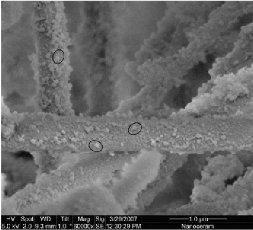
Figure 4.4
Image and schematic of the functioning of the Disruptor™ fiber. Source:
From Figures 5 and 2 from Ref.
95
.
(a) T4-phages are seen attached to the Disruptor™ fiber.
For preparation of the raster electron microscopy (REM) image the filter material was
placed for 4 h in a highly concentrated T4-phage solution and dried afterward. Three
phages are encircled as examples, where the icosahedral head and the tail are easily
visible. (b) Filtration spectrum of disruptor. (For color version of this figure, the reader is
referred to the online version of this topic.)

Search WWH ::

Custom Search