Game Development Reference
In-Depth Information
The maximum-distance vertex of the block at the root of the max-heap is se-
lected to be in the final terrain mesh. That block is subdivided at the vertex
location into two subblocks, the maximum-vertex distances are computed, and the
subblocks are inserted into the max-heap. Because the set of blocks has changed,
thelinearinterpolationofthegraphendpointsmustchange.
Figure10.1(b
)
il-
lustrates this step. Observe that the subblock, whose endpoints are two adjacent
vertices, produces exactly a segment of the interpolation—the graph and linear
interpolation of endpoints are the same for this subblock. After the subdivision,
the figure shows the next root block on the heap and the correspnding vertex of
maximum variation. This process is iterated until the vertex budget has been met.
Figure10.1(c
)
showsadecimatedheightfieldforthecurveof
Figure10.1(a)
after
several such iterations.
In essence, the vertices that deviate the most from low-frequency approximations
of the height values in the blocks are the ones selected for the final triangle mesh.
The large deviations are what our visual systems perceive as contributing to the
“shape” of the height field. Naturally, there is a trade-off between a good-quality
shape and the vertex budget. The artists want more vertices for better visual
quality, but the graphics programmers want fewer vertices for high-performance
rendering.
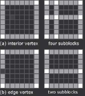
The adaptive decomposition for the two-dimensional height fields is similar to
that for curves. For each rectangular block of vertices, a bilinear interpolation of
the four corner vertices is used as a low-frequency approximation to the height field
of that block. The maximum vertical distance between height field values and the
bilinear interpolation is computed. A max-heap of blocks sorted by the maximum
Figure 10.2.
Block decomposition for a height field.