Graphics Reference
In-Depth Information
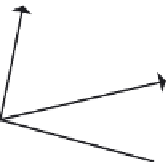
The original unit orthogonal vectors have
ceased to be orthogonal to each other
due to repeated transformations.
Step 1: Normalize one of the vectors.
Step 2:
Form a vector perpendicular (orthogonal)
to the vector just normalized and to one
of the other two original vectors by taking
the cross product of the two.
Normalize it.
Step 3:
Form the final orthogonal vector by
taking the cross product of the two just
generated.
FIGURE 2.14
Orthonormalization of a set of three vectors.
2.2
Orientation representation
A common issue that arises in computer animation is deciding the best way to represent the position and
orientation of an object in space and how to interpolate the represented transformations over time to
produce motion. A typical scenario is one in which the user specifies an object in two transformed states
and the computer is used to interpolate intermediate states, thus producing animated key-frame motion.
Another scenario is when an object is to undergo two or more successive transformations and it would
be efficient to concatenate these transformations into a single representation before applying it to a
multitude of object vertices. This section discusses possible orientation representations and identifies
strengths and weaknesses; the next chapter addresses the best way to interpolate orientations using
these representations. In this discussion, it is assumed that the final transformation applied to the object
is a result of rotations and translations only, so that there is no scaling involved, nonuniform or
otherwise; that is, the transformations considered are
rigid body
.
The first obvious choice for representing the orientation and position of an object is by a 4
4
transformation matrix. For example, a user may specify a series of rotations and translations to apply


Search WWH ::

Custom Search