Graphics Reference
In-Depth Information
spring that models edge
E
23
imparts a restoring force to vertices
V
2
and
V
3
. Notice that the springs push
back against the movement of
V
2
, trying to restore its position, while at the same time they are pushing
the other two vertices away from
V
2
. In a polygonal mesh, the springs associated with mesh edges prop-
agate the effect of the force throughout the object.
If the only springs (or spring-dampers) used to model an object are ones associated with the object
edges, the model can have more than one stable configuration. For example, if a cube's edges are mod-
eled with springs, during applications of extreme external forces, the cube can turn inside out. Addi-
tional spring dampers can help to stabilize the shape of an object. Springs can be added across the
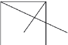
object's faces and across its volume. To help prevent such undesirable, but stable, configurations in
a cube, one or more springs that stretch diagonally from one vertex across the interior of the cube
to the opposite vertex can be included in the model. These springs will help to model the internal mate-
rial of a solid object (
Figure 7.3
)
.
If specific angles between adjacent faces (dihedral angles) are desired, then angular springs (and
dampers) can be applied. The spring resists deviation to the rest angle between faces and imparts a
torque along the edge that attempts to restore the rest angle (
Eq. 7.13
and
Figure 7.4
). The damper
works to limit the resulting motion. The torque is applied to the vertex from which the dihedral angle
is measured; a torque of equal magnitude but opposite direction is applied to the other vertex.
t ¼ k
s
ðyðtÞy
r
Þk
d
y
ðtÞ
(7.13)
Alternatively, a linear spring could be defined between points A and B in
Figure 7.4
in order to
maintain the appropriate angle at the shared edge.
Depending on the size of forces applied to the spring's mass points, the size of the spring constant
(and damper constant), and the size of the time step used to sample the system, a spring simulation may
FIGURE 7.3
Interior springs to help stabilize the object's configuration.
B
A
FIGURE 7.4
An angular spring imparting restoring torques.


Search WWH ::

Custom Search