Graphics Reference
In-Depth Information
hierarchical model used in graphics has objects that are connected end to end to form multibody
jointed chains. Such hierarchies are useful for modeling animals and humans so that the joints of
the limbs are manipulated to produce a figure with moving appendages. Such a figure is often referred
to as
articulated
and the movement of an appendage by changing the configuration of a joint is referred
to as
articulation
. Because the connectivity of the figure is built into the structure of the model,
the animator does not need to make sure that the objects making up the limbs stay attached to one
another.
Much of the material concerning the animation of hierarchies in computer graphics comes
directly from the field of robotics (e.g., [
3
]). The robotics literature discusses the modeling of
manip-
ulators
, a sequence of objects connected in a chain by
joints
. The rigid objects forming the con-
nections between the joints are called
links
, and the free end of the chain of alternating joints and
links is called the
end effector
. The local coordinate system associated with each joint is referred
to as the
frame
.
Robotics is concerned with all types of joints in which two links move relative to one another.
Graphics, on the other hand, is concerned primarily with
revolute
joints, in which one link rotates about
a fixed point of the other link. The links are usually considered to be pinned together at this point, and
the link farther down the chain rotates while the other one remains fixed—at least as far as this joint is
concerned. The other type of joint is the
prismatic
joint, in which one link translates relative to another
(see
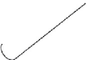
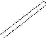
Figure 5.3
)
.
The joints of
Figure 5.3
allow motion in one direction and are said to have one
degree of freedom
(DOF). Structures in which more than one DOF are coincident are called
complex joints
. Complex
joints include the planar joint and the ball-and-socket joint. Planar joints are those in which one link
slides on the planar surface of another. Sometimes when a joint has more than one (
n>
1) DOF, such as
a ball-and-socket joint, it is modeled as a set of
n
one-DOF joints connected by
n
1 links of zero
length (see
Figure 5.4
)
. Alternatively, multiple DOF joints can be modeled by using a multiple-valued
parameter such as Euler angles or quaternions.
Revolute joint
Prismatic joint
FIGURE 5.3
The two basic single DOF joints.


Search WWH ::

Custom Search