Graphics Reference
In-Depth Information
G
1
G
2
E
B
F
B
V
A
G
3
E
A
I
d
I
c
I
b
I
a
G
5
G
B
4
Intersection list of
E
A
:
I
a
,
I
b
,
I
c
,
I
d
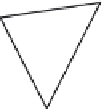
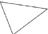
FIGURE 4.38
The intersection list for edge
E
A
.
found, processes subsequent intersections. When this phase is complete all edge-edge intersections
have been found (see
Figure 4.38
)
.
For Object
A
, the intersections have been generated in sorted order along the edge. However, for
Object
B
, the intersections have been associated with the edges but have been recorded in essentially a
random order along the edge. The intersection-ordering phase uses the faces associated with intersec-
tion points and the list of intersections that have been associated with an edge of Object
B
to sort the
intersection points along the edge. The face information is used because numerical inaccuracies can
result in erroneous orderings if the numeric values of only parameters or intersection coordinates
are used to order the intersections along the edge.
One of the defining vertices,
V
B
,
for an edge,
E
B
, from Object
B
, is located within a face,
F
A
,of
Object
A
. Initially, face
F
A
is referred to as the
current face
. As a result of the first phase, the edge
already has all of its intersections recorded on its intersection list. Associated with each intersection
point are the faces of Object
A
that share the edge
E
B
intersected to produce the point. The intersection
points are searched to find the one that lists the current face,
F
A
, as one of its faces; one and only one
intersection point will list
F
A
. This intersection point is the first intersection along the edge, and the
other face associated with the intersection point will become the current face. The remaining intersec-
tion points are searched to see which lists this new current face; it becomes the next intersection point,
and the other face associated with it becomes the new current face. This process continues until all
intersection points have been ordered along edge
E
B
.
All of the information necessary for the combined models has been generated. It needs to be mapped
back to each original object, and new polyhedral definitions need to be generated. The intersections
along edges, kept as parametric values, can be used on the original models. The vertices of Object
A
, mapped to the sphere, need to be mapped onto the original Object
B
and vice versa for vertices
of Object
B.
This can be done by computing the barycentric coordinates of the vertex with respect
to the triangle that contains it (see
Appendix B.2.9
for details). These barycentric coordinates can
be used to locate the point on the original object surface.
Now all of the vertices, edges, and intersection points from both objects have been mapped back
onto each object. New face definitions need to be constructed for each object. Because both models
started out as triangulated meshes, there are only a limited number of configurations possible when


Search WWH ::

Custom Search