Graphics Reference
In-Depth Information
the sphere and that degenerate cases, such as the vertex of one object projecting onto the vertex or edge
of the other object, do not occur; these can be handled by relatively simple extensions to the algorithm.
To efficiently intersect each edge of one object with edges of the second object, it is necessary to
avoid a brute force edge-edge comparison for all pairs of edges. While this approach would work the-
oretically, it would, as noted by Kent, be very time-consuming and subject to numerical inaccuracies
that may result in intersection points erroneously ordered along an edge. Correct ordering of intersec-
tions along an edge is required by the algorithm.
In the following discussion on merging the topologies of the two objects, all references to vertices,
edges, and faces of the two objects refer to their projection on the unit sphere. The two objects are
referred to as Object
A
and Object
B.
Subscripts on vertex, edge, and face labels indicate which object
they come from. Each edge will have several lists associated with it: an intersection list, a face list, and
an intersection-candidate list.
The algorithm starts by considering one vertex,
V
A
, of Object
A
and finding the face,
F
B
, of Object
B
that contains vertex
V
A
(see
Figure 4.37
). Taking into account that it is operating within the two-
dimensional space of the surface of the unit sphere, the algorithm can achieve this result quite easily
and quickly.
The edges emanating from
V
A
are added to the work list. Face
F
B
becomes the current face, and all
edges of face
F
B
are put on each edge's intersection-candidate list. This phase of the algorithm has
finished when the work list has been emptied of all edges.
An edge, E
A
, and its associated intersection-candidate list are taken from the work list. The edge E
A
is tested for any intersection with the edges on its intersection-candidate list. If no intersections are
found, intersection processing for edge E
A
is complete and the algorithm proceeds to the
intersection-ordering phase. If an intersection,
I
, is found with one of the edges, E
B
, then the following
steps are done:
I
is added to the final model;
I
is added to both edge
E
A
's intersection list and edge
E
B
's
intersection list; the face,
G
B
, on the other side of edge
E
B
becomes the current face; and the other edges
of face
G
B
(the edges not involved in the intersection) replace the edges in edge
E
A
's intersection-
candidate list. In addition, to facilitate the ordering of intersections along an edge, pointers to the
two faces from Object
A
that share
E
A
are associated with
I.
This phase of the algorithm then repeats
by considering the edges on the intersection-candidate list for possible intersections and, if any are
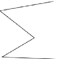
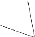
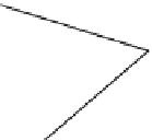
partial mesh from
Object
A
F
B
partial mesh from
Object
B
V
A
FIGURE 4.37
Locating initial vertex of Object A in the face of Object B.


Search WWH ::

Custom Search