Graphics Reference
In-Depth Information
y
x
FIGURE 4.12
Two-dimensional grid deformation relocates vertices in space.
Once this is done for all vertices of the object, the object is distorted according to the distortion of
the local grid (see
Figure 4.12
)
. For objects that contain hundreds or thousands of vertices, the grid
distortion is much more efficient than individually repositioning each vertex. In addition, it is more
intuitive for the user to specify a deformation.
Polyline deformation
A two-dimensional technique that is similar to the grid approach but lends itself to serpentine objects is
based on a simple polyline (linear sequence of connected line segments) drawn by the user through the
object to be deformed [
28
]. Polyline deformation is similar to the grid approach in that the object ver-
tices are mapped to the polyline, the polyline is then modified by the user, and the object vertices are
then mapped to the same relative location on the polyline.
The mapping to the polyline is performed by first locating the most relevant line segment for each
object vertex. To do this, intersecting lines are formed at the junction of adjacent segments, and per-
pendicular lines are formed at the extreme ends of the polyline. These lines will be referred to as the
boundary lines; each polyline segment has two boundary lines. For each object vertex, the closest poly-
line segment that contains the object vertex between its boundary lines is selected (
Figure 4.13
)
.
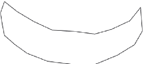
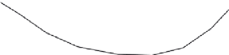
FIGURE 4.13
Polyline drawn through object; bisectors and perpendiculars are drawn as dashed lines.


Search WWH ::

Custom Search