Hardware Reference
In-Depth Information
pin 5, and CS to pin 10. Then, you need to connect the SPI pins to the Arduino board:
MOSI, MISO, and CLK go to pins 11, 12, and 13, respectively.
Then, we'll finish up with the relay module. A relay module has three input pins: VCC,
GND, and SIG, which is the signal pin. Simply connect pin number 6 of the Arduino
board to the SIG pin of the relay module. Finally, connect GND to the Arduino GND, and
the VCC pin to the Arduino 5V.
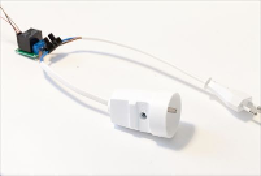
Now we'll make the connections between the lamp and the relay module. You should have
two different cables for that: a male power plug and a female power plug. The following
image illustrates the final result you should get:
A relay module basically has three output pins: COM (for common pin), NC (for normally
closed), and NO (for normally open). What we want is to have the COM pin connected
directly to one pin of the power plug, NC not connected, and NO connected to another pin
of the power plug.
To connect the relay module to the power cables, take the following steps:
1. First, connect one pin of the female power plug to the COM pin.
2. Then, connect one pin of the male power plug to the NO pin.
3. Finally, connect the two remaining cables together, for example, by using a typic-
al electrical screw terminal.
4. Once this is done, you can go on and connect the project to your lamp. The fol-
lowing schematic summarizes the connections between the relay module and the
lamp: