Hardware Reference
In-Depth Information
Hardware configuration
The hardware configuration of this project is not really complex. For each motion sensor
module you want to build, you'll need to do the following steps. The first one is to plug an
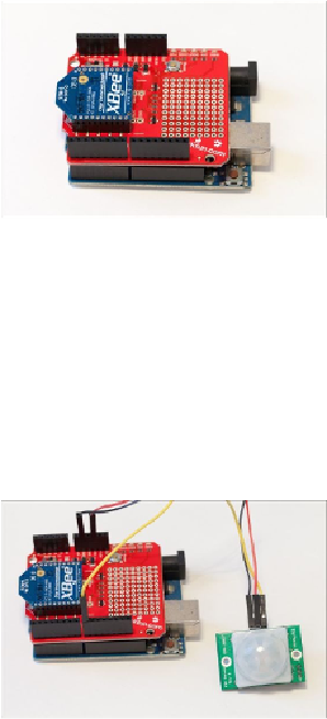
XBee module on the XBee shield. Then, you need to plug the shield into your Arduino
board, as shown in the following image:
Now, you can connect the motion sensor. It has three pins: VCC (for the positive power
supply), GND (which corresponds to the reference voltage level), and SIG (which will turn
to a digital HIGH state in case any motion is detected). Connect VCC to the Arduino 5V
pin, GND to Arduino GND, and SIG to Arduino pin number 8 (the example code uses pin
8, but you could also use any digital pin). You should end up with something similar to this
image: