Information Technology Reference
In-Depth Information
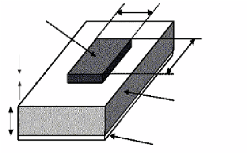
L
Patch
W
t
Dielectric Substrate
h
Ground Plane
Fig. 1.
A microstrip patch antenna [2]
This paper is organized as follows. Section 2 describes the transmission line
model in order to analyze the microstrip patch antenna. Section 3 describes
the design procedure of a microstrip patch antenna. Simulation results of a 2x2
microstrip patch antenna are given in Section 4. Finally, the paper is concluded
in Section 5.
2 Method of Analysis
One of the simplest methods to analyze the microstrip patch antenna is illus-
trated by transmission line model. In a transmission line model the microstrip
patch antenna consists of a transmission line of length L that separates two slots
of height h and width W as shown in Fig. 3. Here the microstrip antenna consist
of a non-homogeneous line of two dielectrics (substrate and air)
A part of the electric field resides in the air and a major portion lies in the
substrate as shown in Fig.2. Due to this the pure transverse-electric-magnetic
(TEM) mode of transmission cannot be sustained in the transmission line as
the phase velocity of the wave is not the same in the air and in the substrate
(dielectric). As a result the dominant mode of propagation in the transmission
line is quasi TEM mode. Due to this an effective dielectric constant is attained
according to Balanis and given [6] by
1+
12
h
W
−
2
reff
=
r
+1
2
r
−
1
(1)
2
where
reff
is the effective dielectric constant,
r
is the relative dielectric constant
of substrate, h is the height of dielectric substrate and W is the width of the
patch.
For the antenna to work in the
TM
10
mode, the length of the patch antenna
must be less than
ʻ/
2(where
ʻ
is the wavelength in dielectric medium) [7,8].
But
ʻ
=
ʻ
0
/
√
reff
(where
ʻ
0
is the wavelength in free space).