Information Technology Reference
In-Depth Information
.
P1 and P2 are constants (4)
The additional constant factor (p2) in the equation improvises the result over
previous work.
The fitness equation of the leakage current for six different models (NMOS, PMOS
and few stacked transistors) have been obtained, then these pre-characterized models
are used to evaluate the leakage current for higher models.
In the design, the transistors in series results in lower leakage current than the sum
of leakage current of the individual transistors. This is stacking effect which is taken
into account by designing models for different combination of inputs. In [1], the
stacking factor was estimated by the average of the values calculated using HSPICE
whereas, in our work, the linear equations derived by curve fitting of the model is
used .Earlier, it was taken as a constant irrespective of the width of the transistor ;
therefore our work has an edge over previous obtained results.
Finally, the individual component's leakage current is summed up to obtain an
analytical equation for the SRAM. These results have been verified by HSPICE
simulations. Also, we have estimated the time required to calculate the leakage
current through our work and also through HSPICE.
4
Analytical Models for Estimation of Leakage Current
SRAMs are the read/write memory which can retain its data till a sufficient power supply
is provided. SRAM storage array, or core, is made up of simple cell circuits arranged to
share connections in horizontal rows and vertical columns. SRAM core consists of
memory cells, read column circuit, write column circuit, row and column decoders.
4.1
SRAM Cell
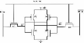
An SRAM cell is the SRAM component storing binary information, as shown in
Fig. 1. The 6T memory cell basically uses two cross-coupled inverters forming latch
and access transistors. Access transistors are enabled during read and write operation.
True and complementary versions of the data are stored on cross-coupled inverters.
The memory cell structure has been taken symmetrical (i.e. P1=P2, N1=N2, N3=N4),
so the characteristics and geometry are same. Thus, they have the same leakage
current. The phases of operation of SRAM are described as follows:
Idle Phase.
In the idle phase, all the word lines are deselected and the bit lines are
precharged to V
dd
. The leakage current for bit=0 is same as for bit=1, replacing N3,
N1 and P2 by N4, N2 and P1 respectively.
Fig. 1.
T Memory Cell Schematic [1]