Information Technology Reference
In-Depth Information
ID Rne Rnw Ren Res Rse Rsw Rwn Rws Cn Ce Cw Cs
0
1
1
1
1
0
1
1
1
0
1
0
1
1
1
1
1
1
0
0
1
1
0
1
1
1
2
1
1
1
1
0
0
1
1
0
1
1
1
3
1
1
1
1
1
0
1
1
0
0
1
1
4
0
1
1
1
0
1
1
1
1
1
0
1
5
0
0
1
1
0
0
1
1
1
1
1
1
6
0
0
1
1
0
0
1
1
1
1
1
1
7
1
0
1
1
1
0
1
1
1
0
1
1
8
0
1
1
1
0
1
1
1
1
1
0
1
9
0
0
1
1
0
0
1
1
1
1
1
1
10
0
0
1
1
0
0
1
1
1
1
1
1
11
1
0
1
1
1
0
1
1
1
0
1
1
12
0
1
1
1
1
1
1
1
1
1
0
0
13
0
0
1
1
1
1
1
1
1
1
1
0
14
0
0
1
1
1
1
1
1
1
1
1
0
15
1
0
1
1
1
1
1
1
1
0
1
0
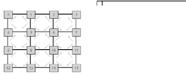
Fig. 1.
Routing restrictions and LBDR bits for XY
3
DyAD and LBDR: A Background
3.1
DyAD-Basics
Dynamic ADaptive Deterministic routing (DyAD) [5] is a novel routing scheme which
integrates deterministic and adaptive routing algorithms by switching between them
when needed. It switches according to the current congestion level at a particular router.
Each router in the network, monitors its local congestion level. If the congestion is low it
works in deterministic mode and enjoys low latency offered by the deterministic routing
algorithm. On the other side it shifts to adaptive mode to avoid congested path when the
congestion is high, resulting in high throughput.
3.2
LBDR-Basics
Logic Based Distributed Routing (LBDR) [11] is proposed as a new methodology for
routing implementation in network on chip (NoC). LBDR aims to provide a simple,
compact and flexible way to represent the topology and captures dynamics of a number
of deadlock free routing algorithms without using routing tables.
To achieve compact and flexible representation of topology and routing algorithm,
each router in the network is configured with three bits per router output port. For ini-
tial 2D mesh, it results in 12 bits for each router. These bits are computed off-line, and
grouped into routing and connectivity bits. Routing bits represent the routing restric-
tions imposed by current routing algorithm for deadlock freedom. Connectivity bits are
used to represent the current network topology.
These bits are computed off-line by analyzing current topology and applying routing
restrictions to represent current routing algorithm. Figure 1 display routing restrictions
corresponding to XY routing algorithm on 4 x 4 mesh and shows the corresponding
routing and connectivity bits for XY routing. LBDR implements routing logic in two
stages. In the first stage, a comparator compares the relative position of destination
router from the viewpoint of the current router. In a second stage, it computes the routing
decision using one logic unit with each output port.
LBDR is complemented with two extra bits per each input port. These bit implement
a deroute option (they code an output port) in case the two previous phases fail in